This thread has been locked.

If you have a related question, please click the "Ask a related question" button in the top right corner. The newly created question will be automatically linked to this question.

ISO1044: in a Digital Isolator, when is a Capacitive Isolation Technology used instead of a Magnetic Isolation Technology?

Part Number: ISO1044
Other Parts Discussed in Thread: ISO1042, ISOW7841, ISOW1044, ISOW7741, ISO7841

Dear Sirs, 

I am looking for information about the Hardware Implementation of the Signals´ Transmission in the ISO1044 Transceiver.

I will list my questions after some key points, however the final question reduces to:

in a Digital Isolator, when is a Capacitive Isolation Technology used instead of a Magnetic Isolation Technology?


Referring to SLLSFB0A ISO1044 Datasheet (“This device” = the ISO1044B = Device Marking for the ISO1044):

“This device uses a silicon dioxide (SiO2) insulation barrier”.


Referring to SLLA564 §2:

“For digital isolators, the primary insulation is provided by thin-film layers of silicon dioxide (SiO2) or polymer-based dielectric applied across a high voltage capacitor or transformer.”


Referring to the video “Reinforced Isolation and Power: An Integration Story

The Isolation Technologies available are Optical, Capacitive and Magnetic, however choosing the Capacitive Isolation Technology does not exclude the use of SiO2 for Magnetic Technology (as per SLLA564 §2).


Referring to SLLA484 (April 2020) Page 2:

“Isolation Reliability: ISO1044 and ISO1042 are based on TI’s SiO2 based capacitive isolation technology.”


Referring to SSZY028 (2017) Page 2:

“This technical brief discusses in detail TI’s capacitor based reinforced isolation for signaling.”

“High voltage (HV) isolation is achieved using two thick SiO2 capacitors in series – one on each side of the isolation barrier.”

Especially Figure 2 of SSZY028 shows how the connection between Transmitter and Receiver is realized using 2 High Voltage Capacitors connected in series, therefore doubling their isolation capabilities.


Questions:

1. No Micro-Transformer like in the ISOW7841 (refer to SLLA368C Abstract) is used in the ISO1044.

  • Is this correct?

2. It is correct to assume the following for ISO1044 Transceivers?

  • there are only Capacitances and SiO2 to implement the Isolation 
  • the Signals´ Transmission relies on Displacement Currents only, with a Maximum Pulse Frequency related to the Rise and Fall Times of the Signals itself
  • there is no modulation of the Signals with a Micro-Transformer an a Carrier in the MHz Range

3. If the answer to Question 2 is "YES": why the same technique is not used in ISOW7841-like devices?

4. If the answer to Question 2 is "NO", given the 3 Channels of an ISO1044 Transceiver:

  • Channel 1 = for the Single Ended Signal “TXD” with return current on Ground 1
  • Channel 2 = for the Single Ended Signal “RXD” with return current on Ground 1
  • Channel 3 = for the Differential Signals at the Pins "CANH" & "CANL" with, for example, Forward Current on "CANH" and Return Current on "CANL"

  • How are the Two separate Single Ended Signals “TXD” and “RXD” of the 8-Pin ISO1044 transformed and transmitted as Differential Signals "CANH" & "CANL"?

5. Why §11.2 of SLLSFB0A ISO1044 Datasheet or §4.2 of SLLA284 suggest to do not use Copper directly under the ISO1044 Transceiver while a Digital Isolator like the ISOW7841 can benefit from an Integrate Stitching Capacitance?

  • Even though with that Stack-Up suggestion the distance of 40 mils is just too much to have a useful Integrated Capacitor it is always better than a Discrete Capacitor Solution, which cannot be effective over 200 MHz due to parasitic effects.
  • Isolation Requirements would in any case be met, thanks to the 20kV/mm Dielectric Strength of the FR4 Material (SLLA368C Page 7).

6. Are there further EMC Recommendations to reduce the Emissions of the ISO1044 (8-Pins) CAN Transceiver other than the ones present in the already above mentioned Literature Documents?

Thanks a lot in advance.

Best Regards, 

MB

  • Hi Mauro,

    Welcome to TI E2E forum!!

    Thank you for your interest in ISO1044 and for going through many technical documents to understand TI isolation technology and the devices. Appreciate your interest and efforts for learning.

    Regarding your questions, please allow me answer individual questions first and then I will come to the question in the title at the end.

    1. No Micro-Transformer like in the ISOW7841 (refer to SLLA368C Abstract) is used in the ISO1044.

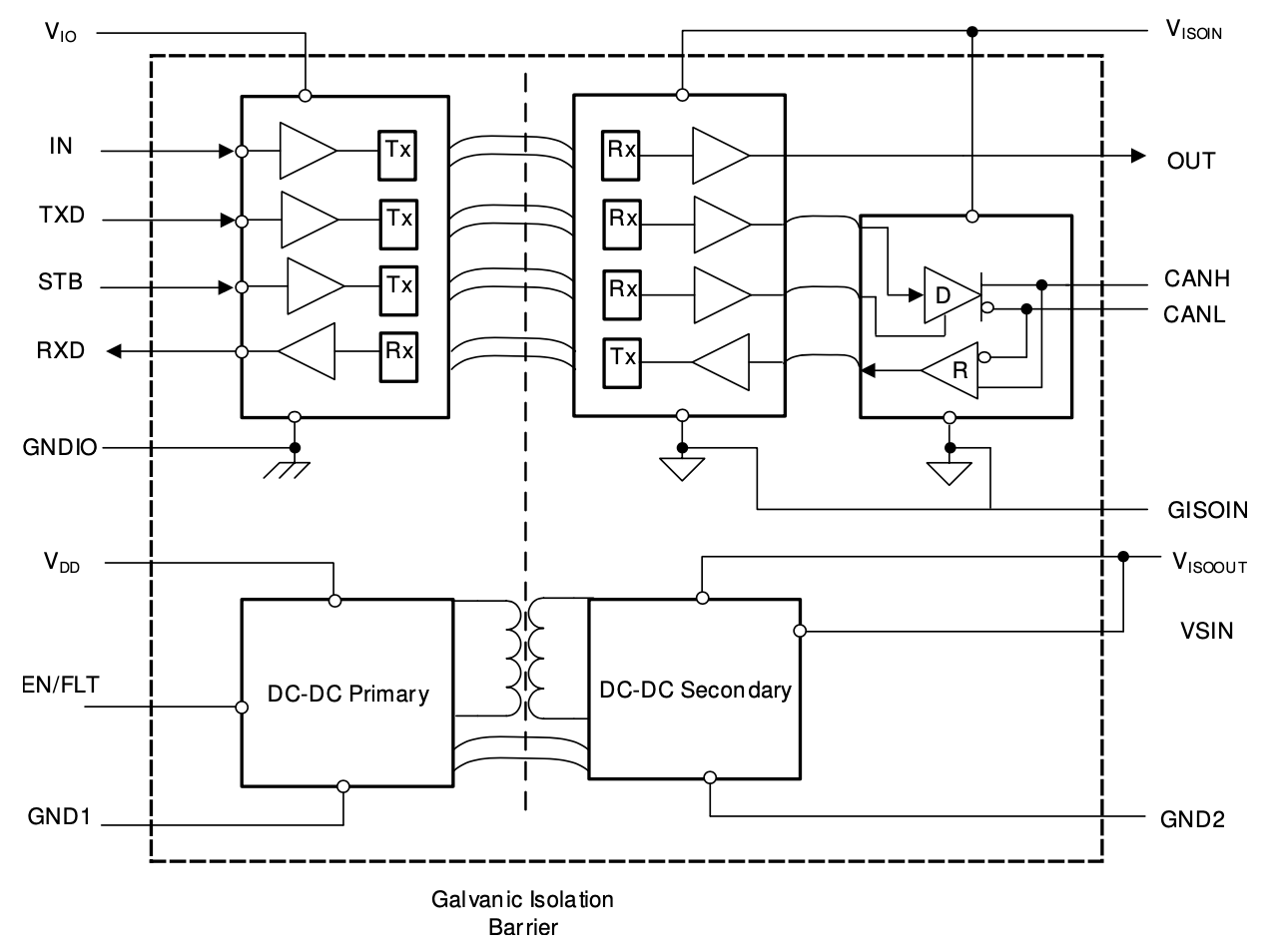
    The micro-transformer mentioned in reference to ISOW7841 refers to the transformer that is used in isolated DC/DC converter which is integrated in ISOW7841. All the data channels in ISOW7841 still use capacitive-based isolation just like it is in ISO1044. Since ISO1044 doesn't integrate isolated DC/DC converter, it doesn't have any micro-transformer in it.

    However, ISOW1044 (notice the extra 'W' in part number) is a DC/DC converter integrated version of ISO1044 and hence, has capacitive-based data isolation channels and a micro-transformer for isolating power. This is represented in the block diagram of ISOW1044, please see below image from the datasheet.

    2. It is correct to assume the following for ISO1044 Transceivers?

    I believe these questions are addressed from the points described in my answer to previous question.

    4. If the answer to Question 2 is "NO", given the 3 Channels of an ISO1044 Transceiver:

    ISO1044 only has two channels for isolating TXD and RXD. These channels are first isolated and then converted to CAN compatible electrical levels. The logic to CAN electrical conversion is similar to that of most non-isolated CAN transceivers. For example, consider TCAN1044 which is a non-isolated version of ISO1044 and it converts single-ended logic signals TXD and RXD to CAN compatible signals on CANH/CANL. Similarly, ISO1044 first isolates the the logic signals and then converts them to CAN compatible signals.

    5. Why §11.2 of SLLSFB0A ISO1044 Datasheet or §4.2 of SLLA284 suggest to do not use Copper directly under the ISO1044 Transceiver while a Digital Isolator like the ISOW7841 can benefit from an Integrate Stitching Capacitance?

    The recommendation of not running any copper in the PCB under the device is a generic recommendation that is applicable for any isolator. Running such copper could reduce the effective isolation ratings that the overall solution could acheive, hence, the recommendation to avoid.

    Since ISOW7841 integrates an isolated DC/DC converter which can pose a challenge in meeting radiated emissions for some applications, the stitching capacitor is recommended as a mitigation plan. Since the stitching capacitor interferes with isolation ratings, it is not desirable to have it but if an application requires it to mitigate radiated emission challenge then one might be required to use it.

    Our second-generation device ISOW7741 has significant improvements done over ISOW7841 and hence, it should meet most application radiated emissions requirements without needing a stitching capacitor. We recommend that you consider using ISOW7741 over ISOW7841 for optimum overall performance.

    6. Are there further EMC Recommendations to reduce the Emissions of the ISO1044 (8-Pins) CAN Transceiver other than the ones present in the already above mentioned Literature Documents?

    Since ISO1044 doesn't integrate an isolated DC/DC converter, we believe it doesn't pose any challenge in meeting isolation related EMC requirements of most applications. If there is any challenge in meeting immunity tests on the CAN bus terminals, then the terminals might need additional protection components like TVS diode. The amount of protection depends on the application EMC requirements. Please see below reference design and refer to its design guide document for detailed EMC test report on the CAN bus. Since these are CAN bus related tests and do not related to isolation barrier, they are equally applicable for ISO1044 CAN bus protection.

    https://www.ti.com/tool/TIDA-00629

    in a Digital Isolator, when is a Capacitive Isolation Technology used instead of a Magnetic Isolation Technology?

    Now allow me to address the final question.
    As you may have noticed, the isolation technology is transparent to the end-user. Both capacitive and magnetic isolation technologies enable signal isolation and end-user might not feel any difference in the way the device behaves externally. Hence, it can't be explicitly said that one is better for an application over the other. What do matter are the device isolation ratings and their electrical and switching specifications. These vary quite a lot based on device and irrespective of the isolation technology used. Hence, it is the overall device specification that defines its suitability for a given application.

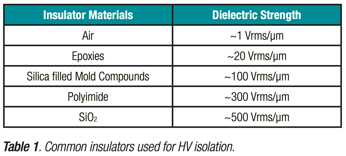
    Since TI isolation devices use SiO2 (that offers high dielectric strength, see image below) as insulation material for isolation, we achieve one of the highest working voltage ratings. For example, ISO7841 in DWW package offers AC working voltage of 2000Vrms and DC working voltage of 2828VDC. This is one of the highest in the industry and hence, TI isolators suitable to be used even in the applications that require highest working voltage requirements.

    I hope this post addresses all the questions you had and helps you understand TI isolation technology and products better. Let me know if you have any other questions, thanks.


    Regards,
    Koteshwar Rao

  • Hello Rao, 

    thanks a lot for the quick and complete reply.

    Have a nice day!

    Best Regards, 

    Mauro

  • Hello Rao, 

    a correction about my sentence "for the Differential Signals at the Pins "CANH" & "CANL" with, for example, Forward Current on "CANH" and Return Current on "CANL"" is necessary, as the following information is important for the PCB Layout.

    The CANH and CANL Signals at the Output of the ISO1044 can´t be "Differential Signals" in the sense of "True Differential Signals".

    "True Differential Signals" (like Twisted Pairs in a Cable) physically differ from the improperly called "Differential Signals" substantially.

    The confusion about this is a problem, when it comes to the PCB Layout of the Tracks of these so called "Differential Signals".

    CANH an CANL are, just as usual, improperly referred to as "Differential Signals" instead of "Complementary Single Ended Signals".

    The same misnomer is to be found in the "Low Voltage Differential Signaling" (LVDS) Components for the same reasons.

    The misnomer is in the following documents and is what led to confusion:

    SLLA279 = Critical Spacing of CAN Bus Connections

    SLLA284 = Digital Isolator Design Guide

    SLLA337 = Overview of 3.3V CAN (Controller Area Network) Transceivers

    SLLA486 = Top Design Questions About Isolated CAN Bus Design

    The major difference is that the Return Current of the "CANH" Track is not on the "CANL" Track, but is on the Return Plane.

    Being "Complementary Single Ended Signals", CANH and CANL are not referenced to each other an they do need a Return Plane for their Return Currents.

    If routed too near each other they will suffer of Crosstalk.

    They are to be routed independently like any other Single Ended Signal, under the requirement that their Electrical Length is equal.

    This to preserve the Timings at the Crossing Point at which they switch and let the Receiver detect their Logic State Change.

    The Datasheet of the ISO1044 SLLSFB0A is actually correct, because it never refer to CANH or CANL as "Differential Signals" but it mentions "Differential Voltages" only, as it should be in such a Transceiver Application.

    Best Regards, 

    Mauro

  • Hi Mauro,

    Thanks for following up with questions related to CAN interface.

    Your understanding is correct, CAN interface is not differential in true sense the way you see for analog differential signals. Although CAN is not truly differential, it does still provide somewhat similar benefits as the truly differential signals by cancelling out the common-mode noise and hence, it isn't necessarily a misnomer if we call CAN differential.

    If routed too near each other they will suffer of Crosstalk.

    They are to be routed independently like any other Single Ended Signal, under the requirement that their Electrical Length is equal.

    Since CANH/CANL lines switch in sync and a CAN receiver reads the difference, we believe it shouldn't have any major impact of crosstalk. We recommend that they are routed together to keep the impedance similar and match to the communication cable.

    Let me know if you have any further questions. If you do have a new question, I would like to request you to post it as a new question with relevant title so that others with similar questions find the answers just by searching the forum.

    You have a nice weekend!


    Regards,
    Koteshwar Rao

  • Good Morning Rao,

    I understand your point of view.

    For those who may view this question it also makes sense to provide the following further Sources of Information.

    Lee Ritchey, Eric Bogatin and Rick Hartley are "gurus" on Electromagnetic Compatibility and Signal Integrity:

    1. "A Treatment of Differential Signaling and its design requirements" (Lee Ritchey)

        https://www.speedingedge.com/PDF-Files/DiffSigDesign.pdf

        One of the greatest articles I ever read.

        It clarifies also why two Termination Resistors are not the same as one Termination Resistor of double value:

        Common Mode noises can´t be filtered with one Differential Resistor.

        Moreover clarifies many of the misconceptions still present today, even though the article was written in 2008.

        Like for example why Signals on a PBC can´t be "Differential Signals" since can´t be twisted (refer to the Paragraph in the middle at page 15).

    2. "Essential Principles of Signal Integrity" (EPSI - Eric Bogatin)

         https://www.bethesignal.com/bogatin/product_info.php?cPath=88&products_id=833

    3. "Differential Signaling Doesn’t Require Differential Impedance" (Lee Ritchey)

        https://www.speedingedge.com/PDF-Files/diffsig.pdf

    4. "SERDES 2 LVDS vs True Differential"

        https://www.youtube.com/watch?v=qEI31nNltFY

        It points out the main differences among "True Differential Signals" and the so called "Differential Signals".

        The main points being the following for "True Differential Signals":

         A. they have two Transformers, one on the TX Side and one on the RX side

         B. their cables are twisted and they are perfectly symmetrical electrically and physically

         C. the Reference for the Return Current of the "positive" (p) Signal is the "negative" (n) Signal,  

              while it is the Return Plane for "Complementary Single Ended Signals" or "Single Ended Complementary Signals"

    5. "What your Differential Pairs Wish You Knew" (Rick Hartley at AltiumLive Keynote 2018)

        https://www.youtube.com/watch?v=QG0Apol-oj0&t=3s

        A video based on the knowledge provided from Lee Ritchey

    After having analyzed the above mentioned source of information it will be clear why referring to "Single Ended Complementary Signals" as "Differential Signals" does not leave space anymore to proper refer to the original "Differential Signals" as it should be and the only way to avoid confusion is to use the adjective "True" for "True Differential Signals".

    But I don´t want to waste time in speaking about the right term to indicate something: the important thing is that the correct knowledge is there to handle the topic correctly.

    It is well known that the usage of proper terms or being detailed doesn´t seem to be of interest.

    When Benjamin Franklin was first experimenting with electricity he had a 50% probability to choose the direction of current flow.

    For one of the Murphy´s Laws he chose the wrong one of course. But this it doesn´t seem to have been a problem since then.

    The whole world didn´t change the Text Books when Joseph Thompson discovered the Electron an the correct Current Flow in 1897.

    It is just known, and everything´s work, so everything is "fine".

    Thank you for your support and I wish you a good start of the week!

    Best Regards,

    Mauro

  • Hi Mauro,

    Thanks for sharing additional information related to differential signals for the benefit of E2E community. Appreciate it.

    I wish you have a good week as well.


    Regards,
    Koteshwar Rao