This thread has been locked.

If you have a related question, please click the "Ask a related question" button in the top right corner. The newly created question will be automatically linked to this question.

ISO1050: Interfacing with other non-isolated CAN transceiver circuits

Part Number: ISO1050


Hello,

I am quite new to the industrial CAN world and I am seeing intermittent issues on my CAN bus. I am seeing one of the nodes not reply for several hundred milliseconds. which leads to random issues happening. This seems to only happen after long periods of operation and the frequency of events increases the longer they are left powered. Once power cycled the issue seems to reset until they are powered for longer periods of time.

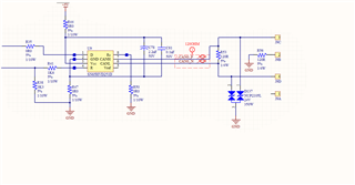
My CAN bus uses isolated transceivers such as the ISO1050, but there are also non isolated transceivers such as the SN65HVD251D. What is the best way to connect these together? Obviously CAN_H is connected and CAN_L is as well, I am using 2 wire shielded cable and it properly terminated on each end of the bus. The cable length is rather short and within the proper spec. However the COMMON pin on the ISO1050 was left open. Where should this be connected to? Should I ground it to the potential of the SN65? Should I switch to a different shielded cabling? 

Thanks,

Matt

  • Hi Matt,

    Thanks for reaching out.

    As a first step, could you please share the schematic to make sure there aren't any issues in it?

    We don't expect any issues in connecting ISO1050 onto a bus with non-isolated CAN nodes. The reference GNDs of all CAN nodes can be connected together through a dedicated wire or shield line but this is optional and the devices should work even without such a connection.

    Could you please confirm the cable length used and the number of nodes on the bus?

    If the issue is happening only after keeping it on for some time then it is possible that this could be related to software. The best way to find out if this is a hardware / software issue, is to monitor ISO1050 MCU side and CAN bus side signals during the time when there is communication issue. If possible, please do try to capture these waveform which would help us debug the issue faster. Thanks.


    Regards,
    Koteshwar Rao

  • Hi Koteshwar,

    Thanks for the replay. However it is quite impossible to monitor the voltages as the site is hours away and the data collection capabilities we have will either not have the proper resolution or enough data size. We are also seeing error frames during these events as well. The system while powered up sends these messages every 60ms and we will not see issues for months but when the issues start to arise they increase to 300ms-900ms or longer within a 10 second range, then the system will then start to work again, but the frequency of these events become more prevalent the longer we wait. The only CAN messages that are having issues are from the ISO1050 circuit.

    The total bus length is 4 meters with 1 stub of 1 meter length with a speed of 250kbits/s (3 nodes). However other designs will use more nodes.

    My main question was with that common pin (pin5 of the 8-pin package of ISO1050) that was left open in the wiring, you are saying we shouldn't have any problems? 

    Thanks,

    Matthew


  • HI Matthew,

    Thanks for sharing additional inputs and the schematics.

    I understand the challenges in capturing waveform of ISO1050 at the time of communication issue.
    Like you mentioned, the cable length, datarate and number of nodes are all seem to be within the spec. Using a different shielded cable shouldn't be necessary.

    My main question was with that common pin (pin5 of the 8-pin package of ISO1050) that was left open in the wiring, you are saying we shouldn't have any problems?

    That is right, we do not expect any issues when the GND pin of ISO1050 is not connected to the GND pins of other CAN nodes. For debug purposes, if it is possible for you to connect them and test, you could try doing so to see if this changes anything.

    The schematic looks good, please find below some comments regarding the schematic.

    1. I didn't see any decoupling capacitor (preferably 0.1µµF) connected between to VCC and GND pins (pins 1 and 4). I am assuming that it is not visible in the schematic snippet shared but is available in rest of schematic and PCB.
    2. VCC2 / GND2 does have 0.1µF decap which is good. It is also useful to have an additional bulk cap of 1µF or 10µF to maintain a stable supply to the CAN transceiver inside ISO1050.
      1. It is also important that the 0.1µF capacitor is placed very close to device VCCx pins (preferably within 2mm distance) so that the device's transient current requirements are met. Not following this practice could lead to device not being operating per the datasheet.
    3. You can also try removing the capacitors C709, C710 & C711, TVS diodes D703 and D704 and CMC L703 to verify if any their capacitance or inductance is affecting overall system performance.
    4. I would also like to point out that the TVS diode SM24 has a clamping voltage of 43V and is not suitable to protect ISO1050 against EMI events. Please see below application note for more details on selection of TVS diode.
      1. How to Design Isolated CAN Systems With Correct Bus Protection

    Please do help comment on the points I have listed out on schematic and let us know if you have any questions, thanks.


    Regards,
    Koteshwar Rao

  • Thanks Koteshwar,

    Unfortunately we do not have control over the ISO1050 circuit as it is from our supplier, but we will continue down another path as it seems the circuitry is good. The overall circuit performance does work as intended. It's just that odd moment in time after long periods of operation where the device stops replying with sporadic error frames. Our discussion on this thread seems to suggest that CAN signals are not the issue, just a symptom of the main cause which is still unknown. I will go through that link you sent me. 

    Thank you,

    Matthew