This thread has been locked.

If you have a related question, please click the "Ask a related question" button in the top right corner. The newly created question will be automatically linked to this question.

ISO3088: Communication failure

Part Number: ISO3088
Other Parts Discussed in Thread: ISO1430, ISO1450

Dear all,

We have used the ISO3088 in previous designs with both Vcc1 and Vcc2 supplied by 5 V.
However, in our current design we are suppliyng Vcc1 with 3.3 V, and we noticed that the communication stops after some time.
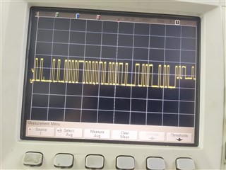
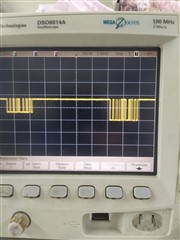
We probed the receiver output (R) signal and we noticed a level shift when the problem happens.

In the images attached you can see that initially we have a signal with 3.3V, peak to peak, and then suddenly it halves.

Could you give us an insight of what may cause this behaviour. The ISO3088 is connected directly to the UART of the microcontroller

Thank you in advance.

  • Hi Ivan,

    Thanks for reaching out.

    Please note that VCC1 of ISO3088 can be either 3.3V or 5V while VCC2 is designed for 5V only and it is expected to work for 5V only, please see below snapshot from datasheet.

    ISO308x family of isolated RS-485 devices is an older family, the latest RS-485 device family is ISO14xx which offers significant performance improvements. ISO1430 or ISO1450 are the suitable devices to be used in place of ISO3088 with the same pin-out while allowing you to operate the device with VCC2 at either 3.3V or 5V.

    Let me know if you have any questions, thanks.


    Regards,
    Koteshwar Rao

  • Dear Koteswar,

    Thank you for your answer. We will certainly look to the devices you suggested for our next designs.

    Howeverr, We have respected the datasheet parameters. Only Vcc1 is at 3.3 V, Vcc2 is still at 5V.

    There is something else we should look after?

    Regards,

    Ivan Bastos

  • Hi Ivan,

    Apologies, I somehow misread your earlier post and misunderstood that VCC2 is being operated with 3.3V but I see that only VCC1 is at 3.3V in your current design while VCC2 is still at 5V.

    The waveform observed indeed is unusual, we do not expect output R to have such an offset. Could you please help me with below information to help debug the issue?

    1. Please share the schematic to review if everything is fine.
    2. Did you test only one unit or have tested multiple units? Do you see this issue happen only on one device or multiple device?
    3. Do you know if there any particular event/test (like EMI) during which this issue happens or does it happen randomly during normal testing?

    This is the first time I have come across something like this in last several years. Please do share as much information as possible to help debug the issue. Thanks.


    Regards,
    Koteshwar Rao