This thread has been locked.

If you have a related question, please click the "Ask a related question" button in the top right corner. The newly created question will be automatically linked to this question.

ISO1640: Datasheet clarification

Part Number: ISO1640

Hi Team,

I am checking the datasheet section "8.4 Feature Description" and I got a bit confused about the device being "pre-charged to VCC/2", why is it not a universal 1V? can you explain this further? 

In addition, what is the difference between precharging to VCC/2 and 1V? can you also explain more about the effect on the bus side?

Thanks for helping.

Regards,

Marvin

  • Hi Marvin,

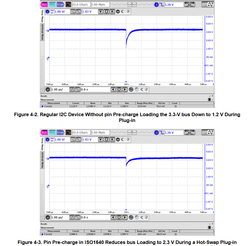
    Thank you for posting to E2E! The ISO164x's I2C bus pins are pre-charged to Vcc/2 to reduce the loading effect seen on the bus when this device is connected during signal transmission. As shown in the image below, and mentioned in How Do Isolated I2C Buffers with Hot-Swap Capability and IEC ESD Improve Isolated I2C? (SLLA548A), a device without pin pre-charge (Figure 4-2) will cause a notable effect on the I2C bus signal which could exceed device HIGH/LOW thresholds, resulting in data corruption.

    The pin pre-charge in ISO1640 reduces the magnitude of the loading effect during signal transmission, shown in Figure 4-3 above. This is also why the pin is charged to Vcc/2. If the pin were charged to 1V, the loading effect could still be excessive if signals on the bus are HIGH instead of LOW. For a pin pre-charge up to Vcc/2, the smaller loading effect is the same whether signals on the bus are HIGH or LOW.

    Please let us know if you have any additional questions.

    Thank you,
    Manuel Chavez