


Other Parts Discussed in Thread: ISO1042, SN74LVC1G17
Hi,
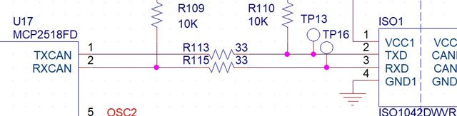
In my design I have the ISO1042DWVR that connects to MCP2518FD with the RX and TX pins (see pictures).
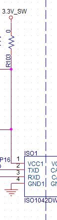
My design is getting the supply from batteries. The VCC1 pin gets 3.3V (with buck power supply from the batteries of 3.3V, and series FET after the buck, then to the VCC1).
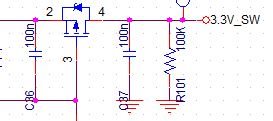
I want that the ISO1042DWVR IC will consume very low current when I do not need to use the communication. So, I added series FET from the 3.3V to VCC1 and I turn on the FET only when I want to communicate (see picture).
from what I understand, when the FET is off then VCC1=0V, and the TX and RX pins can be 3.3V (from the MCP2518FD) and its not allowed to the ISO1042DWVR that TX and RX will be higher than VCC1+0.5V.
When the FET is off there is 100kohm resistor to ground (see picture).
My questions are:
1. Is there another way to set the ISO1042DWVR into sleep mode?
2. Is there a protection diode from TX and RX to VCC1? what is the maximum current allowable of this diode?
3. Is the design looks ok?
PIC 1:
PIC 2:
PIC 3:
Thank you

