Hi ISO team
I am considering replacing silicon lab SI8384 in my customer's new project.
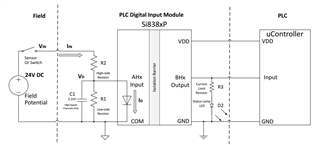
When I compare the pin out of SI8384, we have an extra pin "SENSE" in ISO1212.
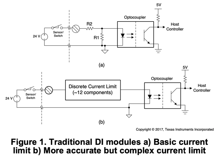
I am quite confused about the purpose of this pin, why we need to add this pin in ISO1212? Why competitor's solution didn't need this pin ?
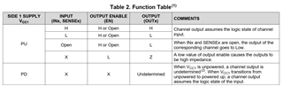
In the datasheet device function table, what's the meaning first column "INPUT"?
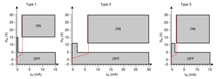
What's the criterion of high level "INPUT"? Is it mean both IN pin and SENSE pin receive high logic?
What's the high logic threshold of SENSE pin? I didn't found this spec in datasheet.