This thread has been locked.

If you have a related question, please click the "Ask a related question" button in the top right corner. The newly created question will be automatically linked to this question.

ISO1042DWEVM: Peripheral circuit design

Part Number: ISO1042DWEVM

Hi Team,

I have several questions about ISO1042DWEVM's schematic diagram. 
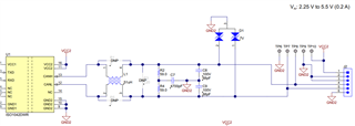
  • Why R2 and R4 is 59Ω rather than 60Ω?
  • Which package do you recommend for R2 and R4? Metric 1206 or 2010?
  • Do we need to add TVS between CANH and CANL for preventing differencial overvoltage?
  • I find that many IC supplier recommend 15V or 24V TVS for isolated CAN becuase the max voltage rating of CANH and CANL is ±70V. Why our schematic diagram suggests -7V/+12V TVS?

Thanks!

BR,

Nison

  • Hi Nison,

    Thanks for reaching out. Here are my answers to your questions:

    Why R2 and R4 is 59Ω rather than 60Ω?

    59 Ω was chosen for these two resistor values because it is a standard resistance value that is typically available for resistors.

    Which package do you recommend for R2 and R4? Metric 1206 or 2010?

    Any resistor package that provides a power dissipation rating of at least 0.25 W can be used for R2 and R4.  

    Do we need to add TVS between CANH and CANL for preventing differencial overvoltage?

    When CANH and CANL are both individually protected, we don't expect the differential voltage to exceed the device ratings. Hence, including a TVS diode to protect against this is optional.

    I find that many IC supplier recommend 15V or 24V TVS for isolated CAN becuase the max voltage rating of CANH and CANL is ±70V. Why our schematic diagram suggests -7V/+12V TVS?

    The part number in the EVM BOM is incorrect. Please use TVS Diodes that are specific for CAN. For information on how to select a TVS Diode for CAN, please refer to this application note: https://www.ti.com/lit/an/slla419/slla419.pdf

     Regards,

    Kenneth