This thread has been locked.

If you have a related question, please click the "Ask a related question" button in the top right corner. The newly created question will be automatically linked to this question.

ISO1452: Transceiver Lightning Protection

Part Number: ISO1452
Other Parts Discussed in Thread: STRIKE, ISO7621

Hello for the ISO1452 Isolated RS485/RS422 Transceiver, I'm assuming it is capable of withstanding the DO-160G Level 4 Lightning Levels?


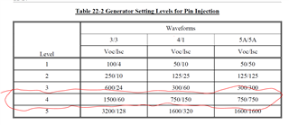
I have attached a screen shot of the voltage/current values for DO-160G Level 4.


Also do you have LTSPICE models for the part? I know there is an IBIS model of the part. However I would still like to simulate how the exposed pins on the Bus would fair if I simulated a lightning strike on the part in LTSPICE simulation.


Thank you,


Johnathan Williams

  • Hi Jonathan,

    Hello for the ISO1452 Isolated RS485/RS422 Transceiver, I'm assuming it is capable of withstanding the DO-160G Level 4 Lightning Levels?

    The isolation barrier for the ISO1452 can withstand up to Level 5 of this standard. That is, if a signal is applied on the bus with respect to GND1. 

    Also do you have LTSPICE models for the part?

    Sorry, we do not have a SPICE model for this part.

    Regards,

    Kenneth

  • Hello Kenneth, even though a SPICE model is not available for ISO1452, is there a way for me to model the interior of the chip, so that I can still simulate lightning strikes when it hits the bus?

  • Hi Johnathan, 

    Can you please confirm where you are trying to apply the lightning strike? Is it being applied on the RS-485 Bus with respect to GND2, or is it being applied on the RS-485 bus with respect to GND1?

    Regards,

    Kenneth

  • It can be applied on the RS485 BUS with respect to either GND. However usually it will most likely be applied with respect to GND2.

    Also is their official documentation stating that the ISO1452 can withstand up to Level 5 of the DO-160G standard? I would like to read it.

    Thank you,

    Johnathan Williams

  • Hi Johnathan,

    For this device, the RS-485 Bus is only rated for voltages up to +/- 18 V. The device also has EMC protections, such as +/- 16 kV IEC 61000-4-2 contact discharge protection and +/- 4 kV IEC 61000-4-4 electrical fast transient protection. Given these parameters, the device will not support up to Level 5 of the DO-160G standard by itself. To meet these requirements, external protection methods would have to be implemented.

    The isolation barrier that separates GND 1 and GND2 is much stronger. As stated by the datasheet, it can support up to 10 kV of surge voltage. We have also tested the isolation barrier specifically for DO-160G standard, and have passed up to Level 5.

    Regards,

    Kenneth

  • I understand the datasheet states that the maximum continuous voltage on the bus pins for this part is +/-18V

    However for extremely short transients like in the 10's of microseconds. Can any pin on the IC experience voltage levels greater than +/- 18V?

    I ask this because the static discharge protection like you said is 4kV-16kV and while it's not the exact same as simulating a lightning strike transient, I feel the reason why 4kV to 16kV of voltage energy (regardless if it's static discharge or a lightning strike) can be applied to the pins is because of the incredibly short transient when that energy is being transferred to the IC through the pins.

    I'm curious to what’s the exact maximum rating for Power Dissipated (Joules/second) or total Energy consumed (Joules) that the specific IC can handle at any pin at any given point in time no matter how short the transient is. This might be better than just straight going off of the absolute maximum ratings for voltage or current a pin can handle since…

     For a generic example:

    Scenario 1. The IC pin sees 100V at 1A for 1usecond = 100Watts for 1usecond or 100 microJoules

    Scenario 2. The IC pin sees 5V at 200mA for 100milliseconds=1 Watt or 100milliJoules

    (Note for example assuming absolute maximum ratings of any given pin are 5V)


    In Scenario 2 for example this can be accomplished by using a large TVS diodes on the pin. Obviously consumes more board space and introduces extra capacitance on the data line.


    In Scenario 1 might just need enough series resistance on the data line instead of additional and larger components. However even though less energy is consumed overall by the part compared to scenario 2 it goes above the absolute maximum ratings but for a significantly shorter duration at just 1microsecond.

    How should I approach this for both the ISO1452 and any other Texas Instrument part#?

    Sorry for the long questions.

  • Hi Johnathan,

    Thank you for sharing all of these additional details.

    Although everything you explained is true, we only guarantee the specifications that are stated in the datasheet, because these are the specifications that we specifically qualify our devices for. More specifically, any EMC tests that we qualify our devices for are explicitly listed in the device datasheet. We cannot guarantee device performance for any test that is not specified by the datasheet, which includes the tests in the D0-160G standard. 

    Additionally, I would also like to point out that ESD only lasts for about 100ns, while surges last for about 100µs. Hence, because of the difference in time duration, passing ESD is much easier than passing surge. Therefore, to pass surge, you will most likely need additional protection components.

    Regards,

    Kenneth

  • 1. I know that there is no SPICE model for this part, however is there a way I can still model the transceiver in LTSPICE? I would still like to gain some data in any way on how it would respond to DO-160G lightning strikes. 

    2. If I were to include additional TVS diodes on the bus pins, what's the max parasitic capacitance to ground I can introduce without attenuating the signal during data transfer?

  • Hi Johnathan,

    I know that there is no SPICE model for this part, however is there a way I can still model the transceiver in LTSPICE? I would still like to gain some data in any way on how it would respond to DO-160G lightning strikes. 

    For this specific device, we do not have a SPICE model. Please allow me some time to check if the non-isolated version of this device has a SPICE model. 

    If you want to test the isolation barrier of this device, you can connect a digital isolator (such as the ISO7621) to another non-isolated RS-485 transceiver. Testing these two together will be similar to testing ISO1452. 

    All of our available models only work with our PSPICE For TI tool, which you can using by download for free from ti.com (here is a link to download the tool: https://www.ti.com/tool/PSPICE-FOR-TI). These models only work for this tool, and do not work for LTSpice.

    2. If I were to include additional TVS diodes on the bus pins, what's the max parasitic capacitance to ground I can introduce without attenuating the signal during data transfer?

    The capacitive load added by TVS diodes on the bus pins will not cause any operation issues with the ISO1452 itself. The additional capacitive load will only impact the rise time and fall time of the signal on the bus. The maximum possible parasitic capacitance that can be present on the bus will be dependent on the maximum data rate that you plan on operating the device at. To estimate the signal rise time or fall time, you can use the following equation: T = 3*R*C, where T = operating rise time/fall time, R=termination resistance on the bus, and C = total capacitive load on the bus. Using this equation, you can estimate the maximum parasitic capacitance that can be present on the RS-485 bus. 

    Regards,

    Kenneth