This thread has been locked.

If you have a related question, please click the "Ask a related question" button in the top right corner. The newly created question will be automatically linked to this question.

ISO1212: Values in the datasheet

Part Number: ISO1212
Other Parts Discussed in Thread: TVS3301

Hi TI team,

I have some questions to understand values in the datasheet

1) How should I unterstand V(iso,func) in the Absolute Maximum Ratings?

It could not be any voltage different between channel 1 and 2 (Vin1 - Vin2), but what does it mean? Are the absolute maximum voltage between:

IN1 - FGND1 is +- 60V

IN2 - FGND2 is +- 60V

IN1 - IN2 is +- 120V with the same ground FGND1 = FGND2

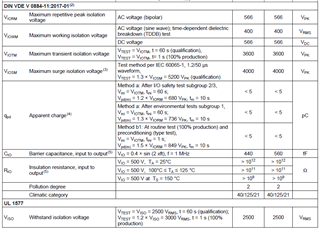
2) The Insulation Specification (as shown below) are only valid between control-side and field-side (Basic Isolation) and not between channel 1 and channel 2 (Functional Isolation)?
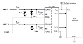
3) We use external EMC device protection but there is a residual voltage of 75V between IN1 - FGND1 (TVS2) or IN2- FGND2 (TVS3) or IN1 - IN2 (TVS1). The field-side grounds FGND1 and FGND2 are connected to same ground. Is the TVS3301 enough for TVS1-3 as protection for the residual voltage of 75V or gives their a better overvoltage solution?
Gerads

  • Hi Davut,

    Thanks for reaching out.

    It could not be any voltage different between channel 1 and 2 (Vin1 - Vin2), but what does it mean?

    V(iso, func) can be understood as a specification that gives the absolute maximum voltage difference that the device can withstand between FGND1 and FGND2. As stated by the datasheet, the device is able to withstand voltage potential differences up to +/- 60 V between FGND1 and FGND2.

    2) The Insulation Specification (as shown below) are only valid between control-side and field-side (Basic Isolation) and not between channel 1 and channel 2 (Functional Isolation)?

    All specifications given by the insultation specifications table refer to the basic isolation that exists across the device, which separates the INx channels from the OUTx channels. They do not refer to the functional isolation between the IN1 and IN2 channels. Therefore, the parameters in the insulation specifications table should only be considered when referring to the basic isolation between the INx and OUTx channels.

    3) We use external EMC device protection but there is a residual voltage of 75V between IN1 - FGND1 (TVS2) or IN2- FGND2 (TVS3) or IN1 - IN2 (TVS1). The field-side grounds FGND1 and FGND2 are connected to same ground. Is the TVS3301 enough for TVS1-3 as protection for the residual voltage of 75V or gives their a better overvoltage solution?

    The clamp voltage of the TVS3301 is under the absolute maximum voltage rating of the INx channels. Therefore, it can be used to provide overvoltage protection for the INx channels.

    Regards,

    Kenneth

  • Hi Kenneth, thanks for your answer.

    V(iso, func) can be understood as a specification that gives the absolute maximum voltage difference that the device can withstand between FGND1 and FGND2. As stated by the datasheet, the device is able to withstand voltage potential differences up to +/- 60 V between FGND1 and FGND2.

    For correctness:

    IN1 - FGND1 is +/- 60V

    IN2 - FGND2 is +/- 60V

    IN1 - IN2 is +/- 120V with the same ground FGND1 = FGND2

    FGND1 - FGND2 is +/- 60V

    am i right with all these values especially with IN1 - IN2 ?

    Regards

  • Hi Davut,

    IN1 - FGND1 is +/- 60V

    IN2 - FGND2 is +/- 60V

    IN1 - IN2 is +/- 120V with the same ground FGND1 = FGND2

    FGND1 - FGND2 is +/- 60V

    am i right with all these values especially with IN1 - IN2 ?

    Your understanding is correct. When FGND1 and FGND2 are shorted together, IN1 - IN2 will be able to support up to +/- 120 V.

    Regards,

    Kenneth