This thread has been locked.

If you have a related question, please click the "Ask a related question" button in the top right corner. The newly created question will be automatically linked to this question.

SN6507: brutally stops and does not start again

Part Number: SN6507

Hi Experts,

Please help tell in which conditions the SN6507DGQR can stop and not re-start?

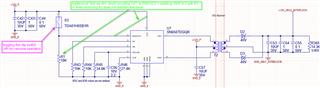
Our customer has checked and they don't have overvoltage (they have 12V VCC) and their current is 100mA nominal, they have a RILIM of around 35kohm (so about 700mA).

Once they have "toggled" (apply GND via 10kohm resistor for a short while and then reconnect to VCC) the EN/UVLO pin the circuit continues to operate properly. 

Best regards,

Gerald

  • Hi Gerald,

    Thanks for reaching out.

    Could you please share the schematic as a first step to review and make sure everything is okay in the schematic?
    Please do also mention what are the design parameters like applied input voltage (assuming 12V), desired output voltage, desired output current, switching frequency, RDC among other things.

    I would also like to know what is connected to EN/UVLO pin, I assuming the circuit that you are going to share will also include this. Thanks.


    Regards,
    Koteshwar Rao

  • Hello Koteshwar and Gerald, I am the initiator of this question and here above you find the schematic and some comments

  • Hi Frédéric and Gerald,

    Koteshwar is looking into this and will provide a review of the schematic at the beginning of next week.

    Regards,

    Kenneth

  • Hi Frederic,

    Thank you for sharing the schematic for review.

    I see that there is a switch used at EN/UVLO pin which connects it to VCC. Could you please confirm if this is a normally-open or normally-closed switch?
    The voltage at EN/UVLO pin must be >1.6V for the device to be enabled and working. Could you please confirm if the switch was closed for testing?

    I also see a note that says RDC and RSR are not mounted, could you please confirm if my understanding is correct?

    If the EN pin voltage is >1.6V and RDC/RSR are not mounted and you are still facing an issue, could you please elaborate in detail what exactly is the issue and when does that happen? Thanks.


    Regards,
    Koteshwar Rao

  • Hi Koteshwar,

    1. The switch is a "bistable" dip switch and can be manually activated either ON or OFF. Per default we have it ON and when the problem occurs we switch it off manually and then ON again and operation resumes. So definitely the voltage on EN/UVLO is much higher than 1.6V.

    2. Yes RDC and RSR are not fitted.

    3 So, the 12 V supply if used to activate a relay (coil, see schematic below). This does not cause any issue as we can "turn on" the relay normally, but the SN6507 suddenly turns off later.

  • Hi Frederic,

    Thank you for your inputs, this helps me understand the issue better.
    Could you please also help me with the below information to help debug the issue?

    1. May I know how long after the relay is turned on does the device turn off?
    2. Does the issue happen all the time or it only happens a few times randomly?
    3. I am not sure if the inductance of the relay is causing an overload current situation as relay doesn't seem to have any current limiting. May I know what is the maximum current expected through terminals 1 and 16 of the relay.?
      1. It might help to limit the current by adding a series resistor in series with the relay.
      2. Alternatively, it might also help to increase the capacitance connected at the 12V rail.
    4. Is it possible to share the voltage and current waveform of 12V output of the SN6507?
      1. Basically the voltage appearing across the relay and the current flowing into the relay.

    Please do help provide your inputs to the above questions to help debug, thanks.


    Regards,
    Koteshwar Rao

  • Hi Koteshwar,

    Before we go in an intensive measurement session can you tell us what are the expected cause for the SN65017 to stop? 

    Here are already some answers to your questions

    1. the time varies, it looks like it has something to do with the signal that is present" or not" on the contacts of the relays (the contacts of the relays are "in theory" galvanically isolated from the coil). As long as we don't have any signal (24V square wave like @ 100kHz) on the relays contacts the SN6507 will operate properly. So I do not expect any issue with the coil itself.

    2. The "stop" happens any time we restart one time, but after toggling the dip-switch it works fine (at least on the first circuit we have tested)

    3 and 4 we will do the measurement later if necessary. The relay is a Panasonic DSP2A-DC12V. It has a 480ohm coil resistance and 25mA nominal current. The start up of the relay is not the problem. So, I am sure the coil itself is not the problem, if there is something wrong it might be the capacitive coupling between the contacts of the relays and the coil, but if so, what could stop the SN65017?

    Thanks

    Frederic

  • Hi Frederic,

    Thanks for sharing the relay part number and addressing many of my questions.

    1. 25mA current into a 480Ω resistance shouldn't be problem for SN6507 and I agree with you that the coil by itself doesn't seem to be an issue.
    2. It is interesting to know that the absence of 24V 100kHz signal on relay contacts doesn't the cause issue while its presence causes it.
      1. You also mentioned that toggling the dip-switch makes it work again every time.
    3. There are many ways SN6507 can be made to not work, the below are some of them I can think of.
      1. VCC below UVLO
      2. EN/UVLO below 1.5V
      3. Exceeding set input current limit (700mA in this case)
    4. I understand that these are well taken care in your design but external factors could interfere and cause these things to be different than what the design intends them to be. I am not sure how the 24V 100kHz signal is playing a role here, the best way to understand that is to look for its traces all across the circuit when device is not working or the moment it starts to fail.
    5. At this time, I think the current into the coil isn't necessarily needed but if you are going to test the board and this is something you can easily capture, then maybe it is worth it to rule out any issues there.
      1. The voltage waveform will be useful to determine what happens to the output when device stops working. If outputs just stays 0V or it turns ON/OFF leaving a lower average DC voltage.
      2. When the device stops working, does the switching completely stop or is it in hiccup where it switches, detects a problem and turns OFF and then repeats? Best way to verify this is to monitor SW1 / SW2 waveform.
      3. Since the dip switch toggling helps the circuit work again, it is worth to monitor the EN/UVLO waveform during when the failure happens and after the failure to see how that voltage varies.
      4. Please also mention if there is anything else that is being done when the failure occurs. Like if there is EMC test, change is 24V signal, a load change anywhere else in your product. Any other similar details will also help debug.


    Regards,
    Koteshwar Rao

  • Hi Frederic,

    I am checking in to see if you have any update on this issue. If you are still seeing the issue and if yes, please do consider conducting the experiments suggested above and share the requested information. Thanks.


    Regards,
    Koteshwar Rao