This thread has been locked.

If you have a related question, please click the "Ask a related question" button in the top right corner. The newly created question will be automatically linked to this question.

ISO7241C: Problem when changing from ISO7241C to ISO7241M

Part Number: ISO7241C
Other Parts Discussed in Thread: ADS1220, ISO7241M, ISO6741

In our design, an MSP430 and an ADS1220 communicate via an SPI isolated by the ISO7241C. This all works without any problem.

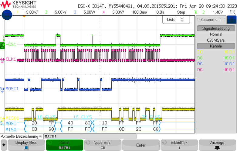
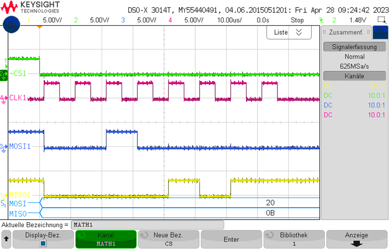
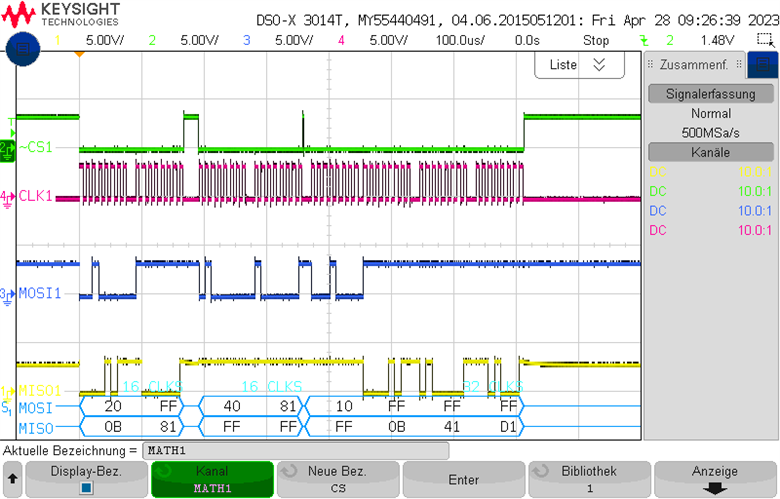
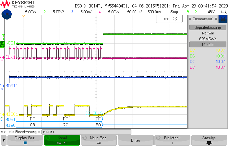
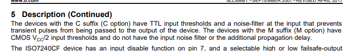
Now we have changed from the ISO7241C to the ISO7241M due to availability. According to the datasheet, the ISO7241M is actually just faster and should work fine for our SPI communication with 100kHz CLK frequency. Unfortunately this is not the case. The communication runs for some seconds before the ADS1220 interprets wrong commands. The behavior of the ADS1220 is not predictable. Sometimes the gain is switched, the next time the sample mode is changed.

There are no other changes in the system. 

Does anyone have any ideas?

Thanks

Stefan

  • Hello Stefan,

    Thank you for reaching out. You are correct, the major difference between the ISO7241C and the ISO7241M is the speed. There are a few parameters such as propagation delay and VIH/VIL limits that differ between the two, but those should not cause any issues. What supply voltages are being used in your application? If you could provide a schematic that would be helpful as well. Do you have any waveforms of the input/output signals?

    One additional note, the ISO7241C and ISO7241M are from an older family of devices. If you are interested in changing to a newer version of these devices, the ISO6741 is a drop in replacement that offers upgraded functionality.

    Regards,
    Darrah

  • Hello Darrah,

    the circuit diagram is basically the following:

    Both sides of the ISO7241 is operated with 3.3V. 

    Waveform of the Input (MSP side):

    and the output side (ADC side):

    What I see is that the isolated MISO signal is slowly running back up after the CS is high again. This of course only happens when the lowest bit was low.

    All measurements were made with the M chip. I will carry out measurements with the C-chip and if I find differences, I will add them here.

    I will test the ISO6741 chip. Let's see how it behaves in my setup. 

    Regards

    Stefan

  • Hello Stefan,

    Thank you for the schematic and these waveforms. It looks like the input MOSI and MISO signals differ slightly from the output, those flipped bits are likely what is causing the incorrect commands. For both cases it looks like a portion of the signal is incorrectly being output as high. What's strange is the rest of the signal is unaffected. Is there any chance that there is noise or transients on your power supplies? It will be interesting to see how the ISO6741 behaves, please do provide measurements/updates on the M version and ISO6741 when they're available.

    Regards,
    Darrah

  • Hello Darrah,

    we have now examined the problem a little more closely.

    In principle, the following sequence is programmed in the data transmission:

    MOSI MISO USE
    0x20 0xXX Command:Read ADC Register (MISO value is first data byte)
    0xff 0x81 ADC Register 
    0x40 0xFF Command: Write ADC Register
    0x81 0xFF ADC Register DATA
    0x10 0xFF Command: Read ADC Data
    0xFF 0xXX Data 1
    0xFF 0xXX Data 2
    0xFF 0xXX Data 3

    The problem we found is that in the MOSI signal on the ADC side additional high bits appear.

    If these bits appear in the commands, the ADC e.g. interprets the command 0x20 of course no longer as a command and then also does not send the corresponding response. However, this response is used to send the settings again afterwards. The sending of the settings is important, because it can also be that a part of the settings is changed. E.g. the ADC channel may be changed without other settings from this byte being changed.


    The error appears much less often (or not at all) if you have connected the oscilloscope on the MSP side. 

    I will check the power supplies. 

    The last 3 bytes in the osci images are the data in the MISO. These can be different. I did not make the images at the same time. So this is not an error.

    Regards,

    Stefan

  • In the data sheet I found the following:

    It is well hidden on page 7 between the revision history of the datasheet and the pinout.  Thereupon I played with Cs against ground. A 1nF capacitor in the CS line on MSP side seems to be the solution. 

  • Hello Stefan,

    Thanks for providing these updates and good catch. Noise that was previously filtered by the ISO7241C now being passed to the output would explain the errors. Since adding the 1nF capacitor, have you seen any more errors?