A related question is a question created from another question. When the related question is created, it will be automatically linked to the original question.
If you have a related question, please click the "Ask a related question" button in the top right corner. The newly created question will be automatically linked to this question.
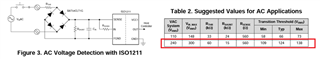
If you apply a sinusoidal waveform at the bridge rectifier input, ISO1211 gets triggered at its VIL and VIH input thresholds and produces a rectangular waveform at the output. Hence, you will see rectangular waveform in sync with the sinusoidal waveform. Let us know if anything is not clear, thanks.
Thank you for sharing additional details of your requirement.
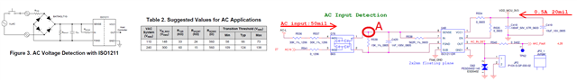
Yes, if your intention is to produce a HIGH at the output whenever the AC signal is present and go to LOW when the AC signal is absent then you can achieve this by adding a bulk cap for filtering.
CIN is added as a noise filter to filter if there is any noise at the input and this cap can be of a small value like 1nF.
For filtering AC or pulsating DC to convert to a steady DC, you would need a bulk cap with much higher value like 10µF or higher. This capacitor should be added right after the diode bridge and before any other components. In this case, just before the resistor RSHUNT.
Since the bulk cap value is large and its job is to maintain a steady voltage, it can take a long time for it to discharge when the input AC is removed. If this time is critical then you can play with the bulk cap value and find the value that works best for both steady DC and reasonable discharge time.
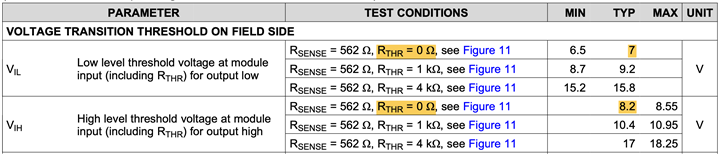
This is device's threshold which is fixed and specified in the datasheet as thresholds for RTHR = 0Ω. Please see below snapshot from datasheet for these thresholds.
Thank you for seeking additional clarification. Please find my inputs below, thanks.
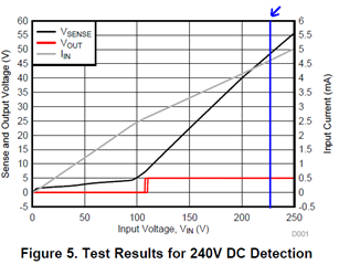
Yes, the capacitor doesn't need to be rated for 220V as it only expected to see voltage of upto 50V and the device VSENSE pin is also rated for 60V. Hence, both the bulk capacitor and CIN only need to support 50V.
Please note that the capacitor actual values derate more than 50% at their max ratings. i.e., a 100V rated 10µF can actually have a value of 5µF or below when applied with 100V. For more details, please refer to the capacitance vs voltage curve in capacitor datasheet.
For this reason, you can either choose a capacitor with double voltage rating or double capacitance than needed.