This thread has been locked.

If you have a related question, please click the "Ask a related question" button in the top right corner. The newly created question will be automatically linked to this question.

SN6507-Q1: SN6507-Q1: Design with duty control and Half-wave rectification

Part Number: SN6507-Q1
Other Parts Discussed in Thread: SN6507

Hello,


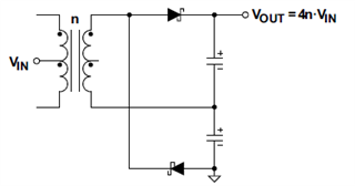
I am thinking of using the SN6507-Q1 for a push-pull gate drive converter.  I would like to use it in Half-wave bridge rectification :

My question is that in this mode, the output current is already continuous, do we need an inductor for duty control? or is this configuration not even compatible with duty control ? 

  • Hi Ali,

    Welcome to TI E2E Forum and thank you for reaching out.

    Since the half-wave rectifier only charges each output capacitor only for half the time, this is going to be more discontinuous than with the full-wave rectifier. Hence, this circuit is going to require more filter than what is needed for the design with full-wave rectifier.

    Duty cycle control can be used with this approach but the overall performance won't be as good as you would find with the full-wave rectifier. If duty cycle is needed, then I recommend going with full-wave rectifier.

    Let me know if you have any further questions, thanks.


    Regards,
    Koteshwar Rao

  • Hello Koteshwar,

    I am afraid that I don't see the relationship between adding an output inductor and the current ripple seen by the chip. Below is the current in the MOSFET of the primary side in the push-pull, I am currently designing, without an output inductor :

    And here is the current with 500µH inductance added on the output : 

    I am confused and curious as to how the chip would react in this mode. 

  • Hi Ali,

    Thanks for further clarifying your question.

    The inductor doesn't affect primary current of the transformer. It is needed to filter the output voltage and provide a smooth DC at the output capacitor.

    When duty cycle control is not used, the duty cycle remains close to 50%. When a full-wave rectifier is used the output capacitor sees a continuous voltage produce by the two diodes each covering the 50% part of each switching cycle leading to output voltage 100% of the time. Hence, no further filtering is needed and output capacitor itself can hold a steady DC output.

    But when duty cycle control is used, the actual duty cycle will reduce to a much lower value than 50%. We recommend that duty cycle is designed to 25% as suggested in datasheet. In this configuration, a full-wave rectifier diode will produce output voltage with each diode covering only 25% of the time leading to output voltage that is only available for 50% duration. Without inductor and capacitor filtering, you will see an output voltage that is 50% in duty cycle. Using output inductor and capacitor, filters out the output signal and produces a smooth DC output voltage.

    When 25% duty cycle is used with only half-wave rectifier, the output of each diode is going to be available only for 25% of the time. To get it to 100%, you would require a much stronger output filter. Hence, LC combination is needed at the output to get a DC output.

    I hope this helps you with clarification and that you will consider using either duty cycle control with inductor filter or no duty cycle control. Thanks.


    Regards,
    Koteshwar Rao

  • Hello Koteshwar,

    Thank you for your answer.

    However, I completely understand the working of a push pull converter I am more than capable of appropriately designing an output filter that allows compliance with the specifications of the DC output, my question is about the operation of the SN6507 and its ability to modulate the duty cycle as a function of the input voltage if I don't add an output inductor. In other words, will this equation remain valid if I don't add an output inductor ? :

  • Hi Ali,

    Yes, the equation applies SN6507's duty cycle irrespective of whether output inductor is used or not. Since the device is an open-loop transformer driver, it switches the internal MOSFETs to the set switching frequency and duty cycle irrespective of what is used on the output side.

    Let me know if you have any other questions, thanks.


    Regards,
    Koteshwar Rao