This thread has been locked.

If you have a related question, please click the "Ask a related question" button in the top right corner. The newly created question will be automatically linked to this question.

ISO1050: Output wrong results on CAN BUS

Part Number: ISO1050

Hi TI experts,

 My customer is using ISO1050 now. In the past, they use one master and ten slaves in one CAN BUS.

 Recently, they want to use one master and 30 slaves in one CAN BUS but failed. (The CAN BUS wire on each board is 30cm. The wire between two boards is 15cm. one machine includes 10 boards. The wire between two machines is 1.8m. So the total length of the whole CAN system is about 30m)

  •  Testing results:

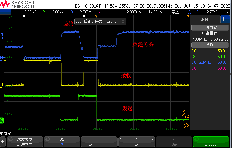
The result is a last part of a packet, which is collected from one of slave. Yellow wire is TX(ISO1050 to F280049). Green wire is RX(F280049 to ISO1050). Blue wire is differential signal on the CAN BUS.

You can see that after a master signal is sent, all the slaves alse responded. But the fall time of blue signal is slow. Eventually, there are 6 cycles of wrong signals on the CAN BUS.

is it due to the connectors and shielded twisted pair they ues? (Capacitor value on the line is so big to make the fall edge slow?)

  • Hi Gary,

    Thanks for reaching out.

    Can you please confirm which pin numbers of the ISO1050 correspond to the different waveforms in the screenshots that you provided? From what you have already mentioned in your previous response, I believe that this is the configuration:

    Pin 2 (RXD) = Yellow Waveform

    Pin 3 (TXD) = Green Waveform

    Pin 7 - Pin 6 (CANH-CANL) = Blue Waveform

    Is my understanding correct? If it is not, can you please share the correct ISO1050 pin numbers for each waveform in the screenshots that you provided?

    Could you also share a schematic that shows exactly how each pin of the ISO1050 is connected in the design?

    Additionally, were these waveform measurements taken directly at the ISO1050 device pins, or were they taken somewhere further away from the ISO1050 device on the CAN bus?

    is it due to the connectors and shielded twisted pair they ues? (Capacitor value on the line is so big to make the fall edge slow?)

    We don't expect any connectors or cables that are rated for CAN applications to have capacitance values that could cause communication errors. From what you have shared, the load on the CAN Bus also appears to be within the recommendations specified by Section 9.2.2.1 of the ISO1050 datasheet.

    Please share the requested information above so that I can work to understand what may be causing this issue. 

    Regards,

    Kenneth