This thread has been locked.

If you have a related question, please click the "Ask a related question" button in the top right corner. The newly created question will be automatically linked to this question.

ISOW1044: CAN output glitch with STB

Part Number: ISOW1044

Hello,

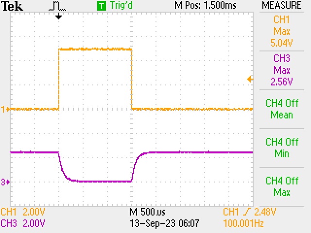
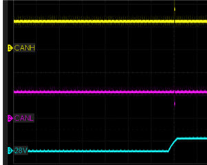
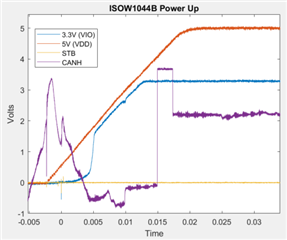
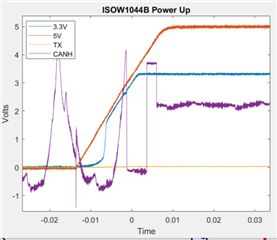
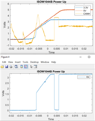
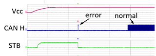
I found when the part powers up the CAN outputs toggle once before waiting for the RX/TX stimulus. This occurred as the power supply was coming up. Originally, the STB pin was tied to ground. I then delayed pulling the STB pin low by about 100ms, and the pulse moves with STB. This power up pulse sometimes causes errors in the PC tool, so I'm looking for a way to get rid of it.

I have VDD powered with +5V, and VIO with +3.3V. The +3.3V is an LDO derived from +5V, so they effectively come up together.

Thank you,

Troy

  • Hi Troy,

    Thank you for reaching out and sharing your observations. Please allow me to test this condition and confirm if this is expected and also provide any suggestions if necessary. In the meantime, please do share your schematic so that I can review the same and make sure everything is okay in it. Thanks.


    Regards,
    Koteshwar Rao

  • Thank you Koteshwar.

  • Hi Koteshwar,

    Following up to see if there has been any success with repeating the observation?

    Thanks,

    Troy

  • Hi Troy,

    Sorry about the delay in coming back to you. I have ordered the EVMs for testing and it is being delivered today. I will be able to test and update you tomorrow or day after. Thank you for your patience during this time.


    Regards,
    Koteshwar Rao

  • Hi Troy,

    Apologies for the delay in come back to you.
    I still didn't get to test the board but I will be able to get back to you tomorrow. Thanks.


    Regards,
    Koteshwar Rao

  • Hi Troy,

    Thank you for your patience,

    I was able to test the EVM to replicate the pulse you had observed but I wasn't able to recreate it. Please see the waveform below along with test setup details.

    VDD = VIO = 5V
    STB = Pulse train tested with various duty cycle from 1% to 50%, frequency tested with 1kHz and 100Hz
    CH1 = STB
    CH3 = CANH

    As you can see from the above waveform, CANH stays recessive (~2.5V) by default when STB = LOW and goes to Hi-Z when STB = HIGH. When CANH is Hi-Z, the voltage drops to 0V and then comes back to ~2.5V once STB is made LOW. I didn't see this expected behavior show up in your waveform and I also didn't see any timing details in the waveform. Please do provide more information related to your test condition so that I can confirm if my testing matches your and if not, I can try to recreate your test conditions.

    Look forward to your inputs, thanks.


    Regards,
    Koteshwar Rao

  • More specifically, in the schematic provided, the toggling is at power up when STB is tied to ground (STB isn't shown in the plot, but it's held at 0V with a direct tie to ground).

  • Hi Troy,

    Thank you for your inputs and the waveform.

    I would like to recreate the issue and for me to be able to do that I will specific details so that I can test with exact same conditions. Specific information like what is the ramp time of VDD of ISOW1044 from 0V to 5V and how many microseconds or milliseconds after STB is held LOW or HIGH and then how many microseconds after this event the glitch happens on CAN bus. A waveform showing time and voltage scales should give this information.

    Please note that it is important to monitor device power supply to recreate and debug this issue. I do understand that the overall system power supply is what you might monitor typically but that doesn't tell me if ISOW1044 is powered at the exact same time. Hence, it would help to monitor VDD of ISOW1044 directly.

    Without this information, my attempts to recreate the failure might not be successful. It might also be possible that only your sample is exhibiting this behavior and not the sample have. To make this conclusion, I would need the same test conditions. If under same test conditions I am not able to recreate the issue on my sample, then I might request you to send your sample to me so that I can test and try to understand the cause. Thanks.


    Regards,
    Koteshwar Rao

  • Koteshwar,

    Here is a plot showing 5V (VDD), 3.3V (VIO), STB (tied directly to ground), and CANH (pin 19 reference to pin 11). Before power application it looks like CANH is high impedance and the probe is picking up 60Hz.

    CANH goes high for about 2.3ms before setting in at 2.5V.

    This is a zoomed out view of the same test set, showing that CAN traffic begins near 205ms after that first CANH pulse.

    This is a different test set that is probing TX (pin 3) instead of STB. It shows it is flat while CANH goes high before setting at 2.5V

    And this shows RX responding to the CANH high state. 

    I realize the datasheet recommends an external pull up on TX, and I am pulling down. Does this cause an issue? There is no external pull up on RX.

    Thank you for your support.

    Troy

  • Hi Troy,

    Thank you for sharing detailed waveform showing the output pulse clearly along with voltage and time scales, this helps me understand the issue better. Please allow me to test the EVM under the same power-up conditions to recreate the issue and come back to you on this.

    During this waveform capture, was TX held LOW or was it floating?
    A LOW TX should make the CAN bus go dominant but I see it is recessive. The TX pin is also internally pulled-up using a 500kΩ resistance which should also make CAN go dominant when the input is floating.

    I realize the datasheet recommends an external pull up on TX, and I am pulling down. Does this cause an issue? There is no external pull up on RX.

    External pull-up on TX pin is optional as the device has internal pull-up. The pull-up on RX is also optional is not necessary for reliable operation of device.

    Please allow me to come back to you with my testing and observations under same test conditions as yours. Thanks.


    Regards,
    Koteshwar Rao

  • Koteshwar,

    TX is pulled low with 4.99k.

    Thanks,

    Troy

  • Hi Troy,

    Thanks for the confirmation.

    CAN standard requires that the CAN bus state is held recessive (logic HIGH) when not in use and goes dominant (logic LOW) only during data transmission on the bus. During all other times, it should stay recessive (logic HIGH). If the bus is accidentally forced with a dominant state (LOW) for longer than 1.2ms, then dominant time out (DTO) kicks in and releases the CAN bus from dominant state and forces it to recessive. DTO is specified in the datasheet as below.

    I see that you are holding TX LOW (dominant) using a pull-down resistor of 4.99kΩ. Due to this, the output first goes dominant (dominant => CANH = H; CANL = L) and when DTO kicks in, it goes recessive (recessive => CANH = L; CANL = H). This is expected behavior. In your waveform, you can also notice that CANH is staying HIGH for about 3ms which matches DTO spec in datasheet.

    It is recommended that TXD pin is not pulled-down using a resistor, rather it should be pulled-up and only driven LOW during data transmission. Since TXD of ISOW1044 has internal pull-up, the external pull-up is optional.

    From the above description, it is clear that this is not an issue rather an expected behavior of device. Please do review this information and let me know if anything is not clear. Thanks.


    Regards,
    Koteshwar Rao

  • Thank you Koteshwar and thank you for the thorough explanation. I greatly appreciate the "why" supporting information. 

    Cheers,

    Troy