Dear Team,
I am using ISO1042BDWV in my design. Below is the schematic. May I know it is fine or not.
Is the placement of 10R resistor is correct or not.

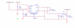
My power supply schematic is given below.

Please let me know your comments.
Regards
HARI
This thread has been locked.
If you have a related question, please click the "Ask a related question" button in the top right corner. The newly created question will be automatically linked to this question.
Dear Team,
I am using ISO1042BDWV in my design. Below is the schematic. May I know it is fine or not.
Is the placement of 10R resistor is correct or not.

My power supply schematic is given below.

Please let me know your comments.
Regards
HARI
Hello,
Thanks for reaching out. Here is my feedback for the ISO1042 in the provided schematic:
-I see that for the termination on the CAN bus, you have connected two separate 60 Ω resistors to ground. While this implementation will still give you the desired 120 Ω impedance between CANH and CANL, it will not provide you with any common mode noise filtering. If you want to have common noise filtering in this design, you will need to connect an additional capacitor to ground between the two 60 Ω resistors. If you require more information on this, you can refer to this technical article: https://e2e.ti.com/blogs_/b/industrial_strength/posts/the-importance-of-termination-networks-in-can-transceivers
-The placement of the 10 Ω resistors is ok. I don't expect this to cause any issues
Other than the feedback on the termination above, the part of the schematic with the ISO1042 is ok.
For the power supply section of the design, can you please provide the part number or the datasheet for the device labeled U72?
Regards,
Kenneth
Hi Kenneth,
My power supply details is given below.
https://www.digikey.in/en/products/detail/mornsun-america-llc/D050505S-1WR3/16915923
Regards
HARI
Hi Hari,
Thanks for confirming the part number of the isolated DC/DC Converter. Unfortunately, since this is not a TI device, we cannot provide any feedback on how it is connected in your schematic, since we are not the experts on this device. To get feedback on how you have this device connected in your schematic, I recommend that you contact the manufacturer of this part.
Regards,
Kenneth
Hi Hari,
Thanks for the update.
Looking at the two schematics that you provided, the only difference that I can see is the added split termination network with a capacitor connected between ground and the termination resistors. If there are any more differences between these two schematics, please let me know.
The added split termination configuration looks good, and should be able to provide additional common mode noise filtering on the CAN bus. The only additional feedback I have is that for the power supply bypass capacitors, make sure that they are placed as close as possible to the device power supply pins in the PCB layout.
Regards,
Kenneth
Hello Hari,
The ISO1042 schematic looks good. If you have no further questions, I will go ahead and close the post. Feel free to open a new thread or reply to this post if you have more to discuss.
Best,
Andrew