This thread has been locked.

If you have a related question, please click the "Ask a related question" button in the top right corner. The newly created question will be automatically linked to this question.

ISOW1412: real-time switch full/half duplex on ISOW1412 design

Part Number: ISOW1412
Other Parts Discussed in Thread: TMUX6222, , ISOM8710, ISO7710

Hi,

As title, I made a design in below block diagram for real-time full/half switching concept with ISOW1412 + TMUX6222.

Can anyone tell me if this is possible? Or suggest me a new solution.

  • Hi Shoes Leu,

    Welcome to TI E2E forum!

    Thank you for sharing the block diagram to explain your use-case. Yes, the approach you are describing to switching between half-duplex and full-duplex dynamically is perfectly fine. The device will work normal and doesn't have any issues with this approach.

    During the full-duplex mode, it is a general practice to turn on driver only during transmission and turn off when not transmitting. This keeps the power consumption down but if power consumption is not a concern then what you have done is perfectly fine. Thanks.


    Regards,
    Koteshwar Rao

  • Hi Koteshwar Rao,

    Thanks for the quick answer and good point to saving transmission power. This is very useful.

    Thank you.

    SHOES

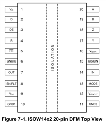
  • I think, that there is a mismatch in the picture above and in the datasheet. In the datasheet, the Output is on the MCU side and the Input is on the Bus side. So I cannot use it as dynamic switch Logic for Half and Full-duplex, or?

  • Hi Martin,

    Sorry, I couldn't completely understand your question. Could you please elaborate what device and pins are you referring to?

    For ISOW1412, A/B and Y/Z are the RS-485 input and output pins. By interconnecting them, the device can be configured to work as full-duplex or half-duplex without any impact on device operation.

    Please do help elaborate your question so that I can better answer your question, thanks.


    Regards,
    Koteshwar Rao

  • Yes, Martin is right.

    in my picture, the OUT pin of ISOW1412 is on devices side with A/B/Z/Y pins, in real world, that OUT pin is on MCU side with R/DE/RE/D (below picture).

    so, it can't work by this picture because the IN/OUT are in wrong side.

  • Hi SHOES,

    Thanks for the clarification and sorry for missing to notice this.

    Yes, I agree the IN/OUT pins of the extra digital channel cannot be used to control the TMUX device. You may have to use a single-channel digital isolator like ISO7710 or an opto-emulator like ISOM8710 to achieve this function. Thanks.


    Regards,
    Koteshwar Rao

  • Hi Koteshwar,

    Yes, I have to add another one isolated GPIO to make it work.

    Maybe one day TI can add a model with different side GPIOs in ISOW1412. ^_^

    Thanks.