Because of the holidays, TI E2E™ design support forum responses will be delayed from Dec. 25 through Jan. 2. Thank you for your patience.

This thread has been locked.

If you have a related question, please click the "Ask a related question" button in the top right corner. The newly created question will be automatically linked to this question.

ISO1228: Please check if my below specifications is matched with ISO1228 part, if that is not matched, suggest me any other part availability.

Part Number: ISO1228
Other Parts Discussed in Thread: ISOM8710, ISO1212, ISOM8110, ISO6741, ISO8110, ISO7740, ISO6740

Specifications:
1.8 Channel Low speed signaling, mixed 24V and 5V single and differential digital inputs and outputs.
2.I/O Interface shall conform to a standard that favors signal integrity over speed.
3.Sinking current input, Sourcing current Output, galvanically isolated.
4.Electrical isolation on each channel.

  • Hello Vaishnavi,

    Thank you for reaching out. Please see my response in line below:

    Specifications:

    1. 8 Channel Low speed signaling, mixed 24V and 5V single and differential digital inputs and outputs.
      1. The ISO1228 devices receive 24 V single ended inputs and does not support 5V. Differential inputs are also not supported.
      2. ISOM8710 can be used to galvanically isolate your solution for single ended 5V inputs.
      3. Can you mention the voltage levels and common mode voltages for your differential signals? 
    2. I/O Interface shall conform to a standard that favors signal integrity over speed.
      1. The devices are designed to meet industrial input standards, such as IEC 61131-2 Type 1, 2, 3.
    3. Sinking current input, Sourcing current Output, galvanically isolated.
      1. Yes, the device is support Sinking current input. The configuration can also be changed for sourcing.
      2. The device can be used in digital output or serial (SPI) mode. 8.3.3 Serial and Parallel Output option
      3. Input side and output are galvanically isolated.
    4. Electrical isolation on each channel.
      1.  Each channel does not have independent isolation. All channels (on the same side) share a ground.
      2. ISO1212 is a two-channel isolator with channel-to-channel isolation. 

    Best,
    Andrew

  • Behalf of Vaishanvi I'm replying to this thread and thanks Andrew for your valuable input.

    • ISOM8710 can be used to galvanically isolate your solution for single ended 5V inputs.

    ISOM8710 is looks it supports only current sink. Does it support current source as well?

    • The ISO1228 devices receive 24 V single ended inputs and does not support 5V. Differential inputs are also not supported.

    Thanks for the detail, we are Ok with single ended input.

    Similarly we have a requirement of 8 channel Digital output interface which should support following specification.

    • Galvanically isolated
    • Should support 5V and 24V single ended and differential ended output
    • Must have sinking and sourcing output support.

    Kindly suggest the suitable part supports above specification.

    Regards,

    Chitharanjan M

  • Hello Chitharanjan, 

    ISOM8710 can be configured to support either current source or sink depending on how the opto-emulator is connected in your system. 

    As stated in my initial post, ISO1228 can support the application of an 8 channel 24V single ended inputs (galvanically isolated) to digital output. ISO1228 does not support 5V input or differential inputs.  

    Can you mention the voltage levels and common mode voltages for your differential signals? 

    In order to see if we have a part that can handle the differential signals, please provide a response to the above question. However, to my knowledge there is no single device to "support 5V and 24V single ended and differential ended outputs" at the same time.  Your application will require multiple devices. 

    Best, 
    Andrew

  • In order to see if we have a part that can handle the differential signals, please provide a response to the above question. However, to my knowledge there is no single device to "support 5V and 24V single ended and differential ended outputs" at the same time.  Your application will require multiple devices. 

    Hi Andrew,

    We are OK with only 24V single ended output. Can you please suggest the suitable part for the same? 

    The device should be galvanically isolated and It should support current sink and source.

    Regards,

    Chitharanjan M

  • Hi Chitharanjan,

    Thanks for clarifying the required voltage levels and signal polarity of the application. From the requirements that you have provided, it sounds like you are looking for isolators that can be used for digital input/digital output modules that are typically found in programmable logic controller applications. If this is not the case, please let me know.

    Here is an overview of the devices we have that are capable of meeting the requirements that you have specified for this application:

    Isolated Digital Input Module

    ISO1228:

    - 8-channel device that is capable of supporting single ended 24V digital input signals

    - Designed to meet industrial input standards, such as IEC 61131-2 Type 1, 2, 3

    - Can be configured to support either sinking or sourcing type inputs

    Configuration for Sinking Type Digital Inputs:


    Configuration for Sourcing Type Digital Inputs:

    -Galvanic isolation between the field side and the MCU side (provided by the device isolation barrier)

    The only requirement that cannot be met by the ISO1228 is isolation between each of the field side input channels, since each field side input channels shares the same ground. However, if channel-to-channel isolation is required, you can consider using the ISO1212, which can meet all of the requirements specified above along with also providing functional isolation between each pair of input channels. 

    Isolated Digital Output Module:

    ISOM8110 w/ a current limiting resistor:

    -Can support a 24V single ended output if a current limiting resistor is used to keep the collector current under the 50 mA limit 

    -Can be connected to support either low-side or high-side driving

    -Provides galvanic isolation between the MCU side and the field side

    Digital Isolator (such as the ISO6741) + Motor Driver

    -Integrated Solution that will use a digital isolator and a motor driver/digital output driver to meet all of the requirements that you have specified

    -For this application, the required digital isolator will be dependent on the required channel configuration

    -For a motor driver recommendation, I recommend that you post a question in the motor drivers E2E forum. 

    If you have any further questions, please let me know.

    Regards,

    Kenneth

  • Isolated Digital Input Module

    Thanks Kenneth Arnold for the detailed explanation.

    So ISO1212 is the suitable Digital IC for my requirement since this is having isolation between the channels.

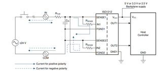
    • Can I use ISO1212 as current sink and source digital input as shown in the below image?

    If I go with the above configuration (sink and source) the single chip I can use it only for one Digital input is it? and for supporting 8 Digital input such 8 ISO1212 IC to be used ?

    As my understanding OUT1 is active when COM is connected to GND for sinking input and OUT2 is active when COM is connected to 24V for sourcing input. So as I said in this configuration one IC can support only one DIGITAL INPUT with the current sink and source configuration. I'm I correct? In this case Host control has to read OUT1 when device in sink mode and read OUT2 when source mode?

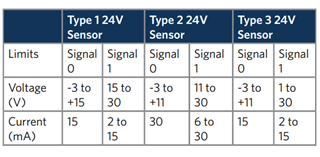
    • As in the ISO1212 datasheet mentioned it "Compliant to IEC 61131-2; Type 1, 2, 3 characteristics for 24-V isolated digital inputs" that means does this ISO1212 support maximum 30mA input as per industrial standard IEC61131-2 Type 1,2,3 as shown in below table 

    Regards,

    Chitharanjan M

  • Hi Chitharanjan,

    Thanks for the update. 

    Can I use ISO1212 as current sink and source digital input as shown in the below image?

    Yes, the ISO1212 circuit that you have referenced is an implementation that allows the device to be used for either sinking or sourcing digital input types.

    If I go with the above configuration (sink and source) the single chip I can use it only for one Digital input is it? and for supporting 8 Digital input such 8 ISO1212 IC to be used ?

    Yes, with this implementation, you will only be able to use one ISO1212 device for one digital input. Therefore, in order for you to have an eight channel digital input implementation, you would need to use eight ISO1212 devices. 

    As my understanding OUT1 is active when COM is connected to GND for sinking input and OUT2 is active when COM is connected to 24V for sourcing input. So as I said in this configuration one IC can support only one DIGITAL INPUT with the current sink and source configuration. I'm I correct? In this case Host control has to read OUT1 when device in sink mode and read OUT2 when source mode?

    Your understanding is correct. With this implementation, the controller will need to read OUT1 to determine the state of a sinking type input and OUT2 to determine the state of a sourcing type input. Alternatively, you could also perform a logical OR operation on the OUT1 and OUT2 signals, so that the result will be a logic high in the event that either one of the OUT pins is a logic high. 

    As in the ISO1212 datasheet mentioned it "Compliant to IEC 61131-2; Type 1, 2, 3 characteristics for 24-V isolated digital inputs" that means does this ISO1212 support maximum 30mA input as per industrial standard IEC61131-2 Type 1,2,3 as shown in below table 

    The current specifications in the table that you provided are the maximum input current values that can be present as a result of the defined voltage thresholds. The input current is not required to be at 30 mA in order for the device to be compliant to this standard. In the case of the ISO1212, the device has a current regulation feature which can limit the current to be between 2.25 mA and 6 mA. Even though this is less than 30 mA, the configuration will still be compliant to the standard because the standard does not require the current to be as high as 30 mA. 

    Regards,

    Kenneth

  • HI Kenneth,

    Thanks for the confirmation.

    Since we running out of GPIO interfaces in the HOST controller, can I Short OUT1 and OUT2 and give it to single GPIO of HOST?

    In this case what would be the OUT2 sate when the device is in sinking mode, Similarly what is the OUT1 state when device in source mode ?

    Regards,

    Chitharanjan M

  • Hi Chitharanjan,

    Thanks for the update. 

    I don't recommend shorting the OUT1 and OUT2 pins of the ISO1212 together. As shown by the function table below, the EN pin will either need to be at a logic high voltage or open in order to read data from either OUT1 or OUT2 (both OUT pins use the same enable pin).

    As a result, no matter what value is read by each INx pin (either low, high, or open), there will always be an instance at which one OUT pin is at a logic high, and the other OUT pin is at a logic low. This will cause the output to be at an undefined voltage between a logic high value and logic low value in the event that both OUT pins are shorted together, and one OUT pin is high while the other OUT pin is low. Therefore, to avoid having an undefined output voltage for one logic state, we recommend that you avoid shorting OUT1 and OUT2 together. 

    To use only one GPIO pin of the HOST controller, you can look into connecting both OUT pins to the input of an external OR gate, and then connecting the single output of the OR gate to the input GPIO pin of the HOST controller. The OUT pin of the ISO1212 should remain low for the input that is not currently being used, which means that the output of the OR gate should only go high whenever the IN pin that is currently being used by the digital input goes high. For an OR gate recommendation, you can post on the logic forum here: https://e2e.ti.com/support/logic-group/logic/f/logic-forum 

    Regards,

    Kenneth

  • Thanks Kenneth for detailed explanation and clarification on Digital Input interface using ISO1212

    Can I use ISOM8110 as Digital output with current sink and source configuration. If so, can you please share the reference circuit which is used as current sink and source output using ISOM8110.

    Regards,

    Chitharanjan M

  • Hi Chitharanjan,

    Thanks for the update.

    It is possible for the ISOM8110 to be used for a digital output module application. However, this will be dependent on the maximum amount of output current that the application requires. The ISOM8110 has a maximum collector current rating of 50 mA, so if the your application requires the output current to be greater than this, then the ISO8110 cannot be used.

    Can you please provide the output current specification that your application requires, so that I can determine if the ISOM8110 can be used?

    Regards,

    Kenneth

  • Hi Kenneth,

    The load current will be around 200mA.So please suggest the part according to this specification.

    Please share the reference design where that particular module is used as current sink and source output. I would like to know how the wiring to be done for sink and source digital output?

    Regards,

    Chitharanjan M

  • Hi Chitharanjan,

    Thanks for providing us with the required load current specification of your application. As previously mentioned, the ISOM8110 has a maximum collector current specification of 50 mA. Therefore, it looks like you will not be able to use the ISOM8110 for your application.

    To meet the load current specification of your application, I recommend that you look into using a discrete solution where a digital isolator is used to achieve isolation, and a motor driver used to drive the current required by the load in your application. Here is a link to a digital output module reference design that uses a digital isolator + motor driver solution: https://www.ti.com/tool/TIDA-00319 

    In the above reference design, the digital isolator that is being used is the ISO7140. While this device will work for the above application, we recommend that you look into using our latest digital isolator devices with upgraded functionality instead, such as the ISO7740 or ISO6740.

    Regards,

    Kenneth

  • HI Keneth Arnold,

     Thanks for the detail.....

    Do you have any part which is similar to ISOM8110 and current support up-to 200mA? (with Integrated MOSFET isolation)

    Also Please let me know how wire to ISOM8110  to support current sink and source digital out? Share me the reference design if you have.

    Regards,

    Chitharanjan M

  • Hi Chitharanjan,

    Thanks for the update.

    Do you have any part which is similar to ISOM8110 and current support up-to 200mA? (with Integrated MOSFET isolation)

    We don't have any devices at this time that are similar to the ISOM8110 that can support a 200 mA load current. As previously mentioned, the best solution that we have for this application is a discrete solution that uses a digital isolator + motor driver, similar to this reference design: https://www.ti.com/tool/TIDA-00319.

    Also Please let me know how wire to ISOM8110  to support current sink and source digital out?

    For digital output module applications where the load current requirement is less than 50 mA, the ISOM8110 can be wired in a high-side/low-side switch configuration, similar to the diagram shown below:

    Regards,

    Kenneth

  • Hi Kenneth,

    Thanks for the detail......

    What is the maximum input voltage that can be provided to V1? Is it 1.4V as per below specification.? or can we operate with 3.3V?

    Regards,

    Chitharanjan M

  • Hi Chitharanjan,

    What is the maximum input voltage that can be provided to V1? Is it 1.4V as per below specification.?

    The ISOM8110 does not have a maximum input voltage specification for the voltage that can be applied across the AN and CAT pins. Instead, the device has a maximum input forward current specification of 50 mA. The input forward current that passes through the AN and CAT pin of the device cannot exceed 50 mA, or else the device may be damaged. The 1.4 V specification that you have identified refers to the forward voltage drop that occurs across the AN and CAT pins of the device. It is not a specification for the maximum input voltage that can be applied to the AN pin of the device. 

    or can we operate with 3.3V?

    As long as a current limiting resistor is used to limit the device input current such that it is less than 50 mA, a voltage of 3.3 V can be used at the AN pin of the device. 

    Regards,

    Kenneth