Customer is interested in this part and did some SIM results with given Pspice model.
Please help to confirm if below descriptions are ok.
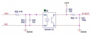
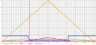
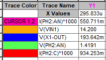
1. When VIN1 goes up to 14.2V, the X1-OUT is about 193mV.
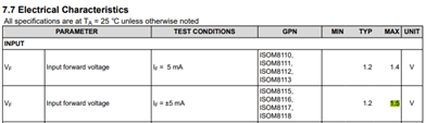
2. VAN = VF = 1.42V, is this VF value set in the Pspice model? it is fixed one?
In the d/s, the max. value is 1.4V. why it's set with 1.42V higher than 1.4V?
3. IF calculation
(14.2-1.42)/5.6K-1.42/820 = 0.55mA. it has the same result with Pspice model/SIM.
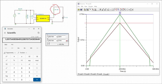
4. The Sim result of the IC is about 0.935mA , the calculation result is (3.3-0.19)/10K = 0.31mA. Why there are difference?
5. CTR
CTR = 0.934 / 0.55 = 170% (SIM Result),CTR = 0.31 / 0.55 = 56% (Calculation Result),
CTR is set in PSpice Library = 120%. is this fixed value?
There are three different CTR values, it looks there are in 50% to 195% range at IF=0.5mA. Which one is close to real application?