This thread has been locked.

If you have a related question, please click the "Ask a related question" button in the top right corner. The newly created question will be automatically linked to this question.

ISOW1412: Ferrite beads (FBs) recommendation value

Part Number: ISOW1412

Hello team,

Can you give us an advice on FBs selection? 

  • Application Brief (https://www.ti.com/lit/an/slla561/slla561.pdf) says that "Choose these FBs such that they offer the highest impedance (> 1 kΩ) at the switching frequency and its harmonic frequencies.".
  • In our understanding, the switching frequency of ISOW1412 is 25MHz.
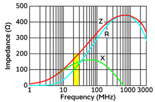
  • But BLM15EX331SN1 which is recommended in datasheet does not meet the condition in the Application Brief.

--> Which is material we need to follow?

Best regards,

Shotaro

  • Hello Shotaro-san, 

    Please allow me to review with the team and get back to you. 

    Best,
    Andrew

  • Hello Shotaro-san,

    We suggest using the datasheet BLM15EX331SN1 as a good starting point. If further attenuation of signals is needed, then please follow the app note guideline to "choose these FBs such that they offer the highest impedance (> 1 kΩ) at the switching frequency and its harmonic frequencies."

    Best,
    Andrew

  • Hello Andrew-san,

    Thank you for supporting!

    Do we have any criteria when customer select an alternative part with BLM15EX331SN1?

    For it, customer referred the app note, but it does not make sense because of datasheet BLM15EX331SN1.

    Best regards,

    Shotaro

  • Hi Shotaro-san,

    Sorry about the confusion. Since radiated emissions testing typically starts from 30MHz and 25MHz is outside the emissions band, the FB didn't require to be chosen to attenuate 25MHz. But if customer needs to meet an emissions standard where emissions at 25MHz is also critical then they would have to choose an FB that has good attenuation at 25MHz as well.

    The App Note refers to CISPR 32 and the chosen FB is sufficient to meet this standard. Although 1kΩ impedance is the guidance, the EVM didn't require it to be 1kΩ to meet emissions requirement, that's why a lower impedance value was used to evaluate. But for customer applications where the PCBs are expected to be bigger in size, we recommend following the guideline of 1kΩ for choosing FB. Let me know if this answers your question, thanks.


    Regards,
    Koteshwar Rao

  • Hi Rao-san,

    I explained the above contents. Thank you very much. And the below is additional questions. Can you give me your knowledge?

    1. Do we have any recommendation value for FB like xxΩ from A MHz to B MHz? The customer wants to follow the guideline.

    2. You told that if PCBs are expects to be bigger, large impedance is recommended. Can you tell me the reason?

    Best regards,

    Shotaro

  • Hi Shotaro-san,

    Thank you for following up with additional questions.

    Radiated emissions of customer application are not only dependent on the ISOW1412 but are also dependent on other factors like PCB size, all connecting cables and its enclosure type. These factors can make the emissions higher and there is not an easy way to predict the final results.

    1. Due to the above reason, there is no definite value of FB that is going to suppress radiated emissions sufficiently for all applications. This has to be tested and then updated as and when necessary until the results meet customer requirements.
      1. Impedance of 1kΩ from 30MHz to 1GHz is the value that we know will help for most customer applications and that is our recommendation. Higher the impedance, higher would be the emissions suppression.
      2. Smaller PCBs might not necessarily need 1kΩ impedance. ISOW1412 EVM only requires 330Ω of impedance to meet emissions requirement. This was identified through testing.
      3. If customer PCB is small in size as the EVM then they could also consider 330Ω FB but if they expect larger PCB, then we recommend choosing an FB with higher impedance.
    2. PCBs connected to ISOW1412 act as an antenna and the radiations from ISOW1412 will be radiated more easily.
      1. Bigger PCBs means larger antenna or an antenna with higher gain. This can lead to more emissions being radiated.
      2. Due to this, higher impedance FBs are needed to attenuate more noise.

    Let me know if you still have any further questions, thanks.


    Regards,
    Koteshwar Rao