This thread has been locked.

If you have a related question, please click the "Ask a related question" button in the top right corner. The newly created question will be automatically linked to this question.

ISO1042DWEVM: ISO1042DWEVM

Part Number: ISO1042DWEVM
Other Parts Discussed in Thread: ISO1042, ISO1050

Hello,

I use ISO1042 in a design.

I'm doing a simulation to see the level of current in the differential inputs, CANH and CANL  with 1200V/1Ohms générator across the emc filter inputs (with protections like TVS).

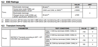
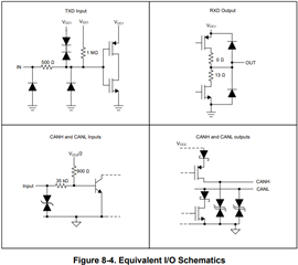
Which kind of structure there is between CANH, CANL and VCC2/GND2? A type of ESD diode/zener? Inside the specification I see that the voltage must be lower than 70V. After 70V there are some diode activated?

I don't care if I will destroye the component. I just want to estimate the input current if the input voltages (CANH, CANL) increase more than 70V (and let's say stay below 90V for instance for at least 10µs).

Best regards,

  • Hello Christophe, 

    Thanks for reaching out. If this is regards to ESD strikes and protection, the device is tested to ISO7637-2 Transients according to GIFT - ICT CAN EMC test specification. 

    If the voltage over 70V is a transient with a duration outside of the spec, then exceeding 70V on the bus violates the absolute maximum conditions and the device may get damaged.

    There is not equivalent I/O schematic for ISO1042, but I believe the ISO1050 below equivalent I/O schematic for ISO1050 can be used as a reference.   


    Let me know if this helped and feel free to follow up if you have further questions. 

    Best,
    Andrew

  • ,Hello,

    The given equivalent IO schematic is really hepful. Thanks a lot.

    The transil for canh,l output have 70V breakdown voltage, right?

    Could you tell us the diameter of the bounding on canh,l, one or two bounding per single output? We want to see whether the bounding on canh , canl will brake or not with a ramp of current of 3µs that will reach 4A (after this time voltage/current protection will be activated), or may be the transistor or diode... Important thing for us in this application, is that the isolation barrier will be not broken. I undestand that you will not guarantee the behaviour of this component with this current pulse.

    Regards,

  • Hello Christophe, 

    What do you mean by:

    the diameter of the bounding on canh,l, one or two bounding per single output

    I am unfamiliar with this term. However, it sounds like you are looking for additional bus protection. We do recommend CAN bus protection diodes, see How to Design Isolated CAN Systems With Correct Bus Protection for more details. 

    In the event that the device is damaged (primary failure), isolation will be maintained as long as 6.9 Safety Limiting Values are not exceeded. Following safety limiting values will make sure the device does not heat up and cause a secondary failure as a result of a sustained over voltage. It may not be directly relevant but please see Understanding failure modes in isolators for more details. 

    Best,
    Andrew

  • Hello,

    Could you provide the rdson of MOS transistor referring to figure 8-4 of iso1050 data sheet for iso 1040 for CAN H and CAN L output?

    Thank you,

    Best regards,

    Christophe

  • Hi Christophe, 

    Unfortunately, the exact value would be under NDA. You can assume a typical CMOS Rdosn of about 0.1 Ohms.

    Best,
    Andrew