This thread has been locked.

If you have a related question, please click the "Ask a related question" button in the top right corner. The newly created question will be automatically linked to this question.

ISO7741: Can ISO7741 support the resolution of HRPWM due to Pulse width distortion(PWD)?

Part Number: ISO7741

Thanks for reading this message.

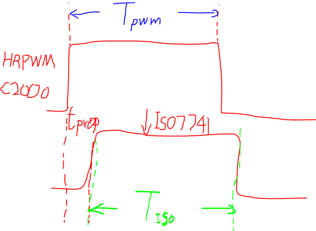
The HRPWM in C2000's time step is about 150ps class, it is very precise.

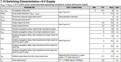
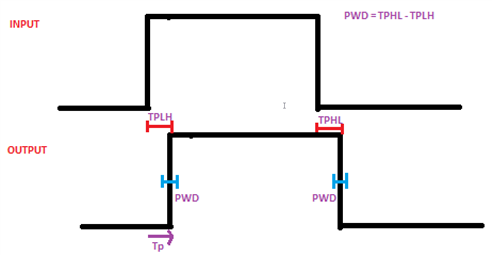
But i see that there is a pulse width distortion time in ISO7741 datasheet, so i want to know that if this PWM or other specs in ISO7741will reduce the resolution of HRPWM?

Is this PWM a constant or it regards with other parameters, like frequency, voltage and temperature?

|Tpwm - Tiso| = ?

Thanks!

  • Hello,

    Thank you for your question.

    Yes, the pulse width distortion will have an effect on the PWM of the C2000. The pulse width distortion is defined as |TPHL - TPLH|. Please see figure 8-1 in the datasheet, which is shown below, for more information:

    The PWD is a constant specification. There are different PWD specs per voltages in the recommended operating conditions. The timing specifications in table 7.15 (shown below) are dependent on the process and temperature of the device. 

    Regards,
    Aaditya Vittal

  • Hi Aaditya,

    Thanks for you detailed reply!

    So does it mean in a certain temperature and 3.3V to 0V level's switching period (HRPWM), a single device's PWD is always the same? 

    For example, we'll send 50ns pulse, in the other side we will get for instance 45ns. But if we send 50.15ns pulse, will we get 45.15 on the output?

    Best Regards,

    Bowen

  • Hi Bowen,

    Thank you for your question.

    Yes, the PWD for a device is always the same at a given voltage. The PWD value we have presented in our datasheet accounts for the conditions in the recommended operating conditions, such as the temperature range.

    For example, we'll send 50ns pulse, in the other side we will get for instance 45ns. But if we send 50.15ns pulse, will we get 45.15 on the output?

    From your example: If the PWM is 50ns, the output from the isolator can be 50ns ± 4.9ns.

    Regards,
    Aaditya Vittal

  • Hi Aaditya,

    Yes, I understand it is a fixed value.

    From your example: If the PWM is 50ns, the output from the isolator can be 50ns ± 4.9ns.

    But from your answer, sorry it might be a little confused for me, does it mean the output can be in a certain range? Like the chip i use, if the PWD is +0.5ns in 25C and 3.3V level HRPWM, is Tout always Tin+0.5ns? (Tin is the input pulse width, Tout is the output pulse width)

    Thanks!

    Best Regards,

    Bowen

  • Hi Bowen, 

    Thanks for your reply.

    Yes, the output can be a certain range given the PWD.

    Like the chip i use, if the PWD is +0.5ns in 25C and 3.3V level HRPWM, is Tout always Tin+0.5ns? (Tin is the input pulse width, Tout is the output pulse width)

    Taking the PWD into account, The 0.5ns would be added or subtracted to the rising edge or the falling edge of the pulse width itself. You can think of the PWD as the "tolerance" to the propagation delay. 

    Shown below is a picture that hopefully gives a better understanding of the PWD:

    As you can see, there is PWD on the rising edge and falling edge of the output waveform. This means that the PWD, although a set value of 4.9ns, can act independently on the rising or falling edge. So, the PWD can add or subtract to the rising edge while also adding or subtracting for the falling edge.

    Please let me know if this helps.

    Regards,
    Aaditya Vittal

  • Hi Aaditya,

    Thanks for your patience.

    So maybe it will be meaningless to use HRPWM if a high PWD exists...

    Best Regards,

    Bowen

  • Hello,

    Thanks for your reply.

    Yes, The isolator would affect the resolution of the HRPWM. 

    Regards,
    Aaditya Vittal