


Hello all,
I am noticing an issue when testing with component ISOW7721 that I have not been able to solve so far.
I am using this component is a board which will be used to measure HVDC.
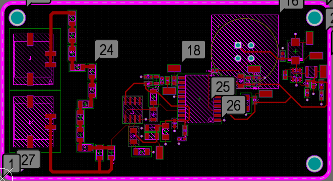
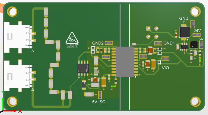
Below you can find the schematic of my circuit and the PCB:
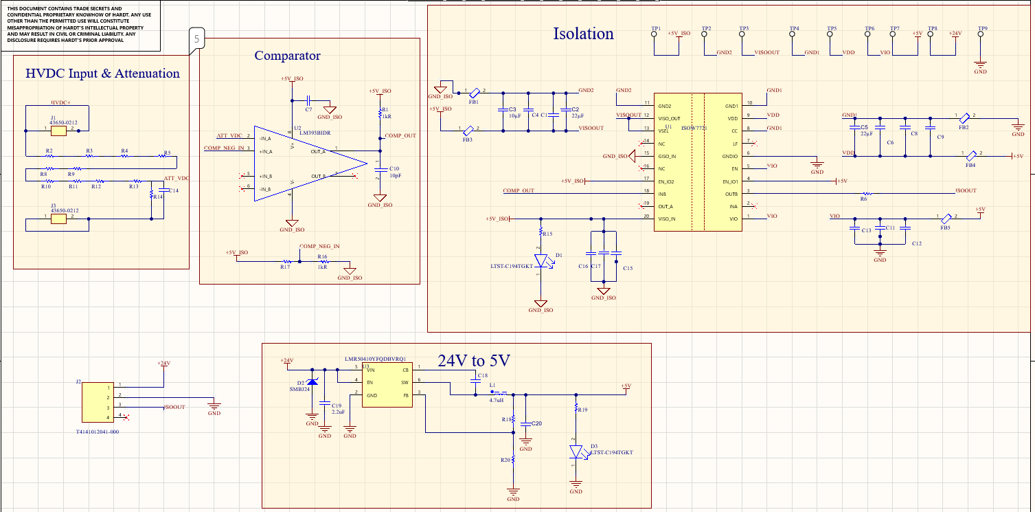
The circuit consists of 3 subsystems:
1. The first one is just a voltage divider, where the HVDC input is attenuated to a lower voltage.
2. The second one is a comparator which compares this attenuated voltage to a certain pre-set threshold level. The idea behind this subcircuit is to essentially be notified whenever there is HVDC present in the system above a certain value/amplitude.
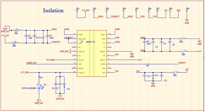
3. The third part is the subcircuit containing the re-inforced digital isolator. The idea behind this subcircuit is to essentially transmit this High level logic (when HVDC> Certain amplitude) to a LV Control System. So the HV side of the system is isolated form the LV side.
After soldering the components I conducted some pre-liminary tests to see if the circuit works. Since the HVDC that this board is designed for is very high and not convinient and available at this point in time in my project, I decided to use a (pulse) signal generator from an oscilloscope and inject this signal somehwere along the resistor devider, such that the attenuated voltage I get from there, would match the attenuated voltage I would get when the HVDC would be present and the whole chain fo the resistor deviders will be used.
The 24V supply for the board was generated by another LAB DC Power supply.
The tests seemed to be succesful and I was getting exactly what I was expecting. Below you can see the pictures from the test resutls, as measured on the oscilloscope.
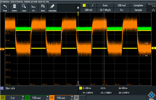
PICTURE 1:
OrangeTrace is the 1st input of the comparator, in this case representing the HVDC (generated a pulse to represent the HVDC since I wanted to have a clear and visible result for the way the chip is operating)
Green trance is the 2nd input to the comparator, which is generated by a simple voltage divider (COMP_NEG_IN if yu refer to the schematics)
Yello Trace is the output of the comarator (COMP_OUT, if you refer to the scematics)
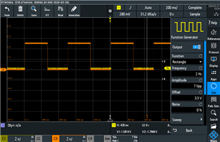
PICTURE 2
Traces for: COMP_OUT & ISOOUT if you refer to the scematics.
Up until this moment everything seemed to be working as expected.
A few days after I conducted the first tests, I wanted to review a few details. This time however, I was not able to measure ISOOUT despite the fac that COMP_OUT was still being transmitted to the relevant pin on the Isolator chip. Everything on the left-hand side of the board is wokring properly. All the voltage and supply rails on the right-hand side of the board are also working properly. All the supply pins on the right-hand side of the chip are still getting supply by the corresponding voltage rails. For some reason however, I am still unable to measure ISOOUT.
To make things more interesting I decided to test the operation of th echip in the reverse direction .
So instead of having a signal injected into pin18 IN_B and measuring the output of the chip on pin3 OUT-B, I injected a pulse signal on pin2 IN_A and measured the output of the chip on pin19 OUT_A.
To my surprise I could actually measure the output signal in this case.
If anyone has any ideas of what might be going on, or any recommendations, I would really appreciate your feedback.
Best regards,
Konstandin Kotsis

