This thread has been locked.

If you have a related question, please click the "Ask a related question" button in the top right corner. The newly created question will be automatically linked to this question.

ISO1042: ISO1042 Isolated CAN Transceiver With 70-V Bus Fault Protection and Flexible Data Rate

Part Number: ISO1042

Hi,

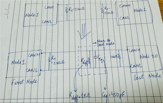
I want to test the working of the CAN Transceiver for which I need to connect 28 nodes between TX and RX node. So, instead of adding multiple nodes to increase propagation delay, rise time and fall time, can I add the capacitance on CANH and CANL of the last node.

For eg, as mentioned in TI datasheet, Max Input capacitance to ground is 30pF(CANH or CANL) 

Now, for replicating 28 nodes, Can I add 28*30 = 840pF each on CANH and CANL of the last node. 

As per my understanding this would help in replicating 30 nodes. 

Please let me know if my understanding is correct or not.

If not, how can I replicate the effect of 28 intermediate nodes without adding actual nodes?

Thanks.

  • Hi Vishal, 

    Yes, you should be able to replicate multiple nodes by adding a resistor and capacitor across the CANH and CANL. To calculate the R and C value needed use the differential resistance and capacitive values from the datasheet (see below) and multiply by the number of nodes. 

    This would mean C = 15pF(30nodes) = 450pF and R = (30kohms/30nodes) = 1kohms

    I hope this helps.

    Best,
    Andrew

  • Hi Andrew,

    Thanks for the response. It was very helpful. For confirmation, can you see the below figure and confirm if this setup is fine?

    One more query, to attain the worst-case scenario, should I not be taking the Differential Input Resistance to be the maximum value (80k) instead of the minimum value(30K) that you mentioned in the last reply?  

    Thanks and Regards,

    Vishal

  • Hi Vishal, 

    The above schematic looks good and would be the correct values to emulate 30 nodes on the bus plus a 1-node as the last node (31 total). 

    Typically, the minimum resistance is the worst case since the lower bus resistance would draw more current. However, if for some reason the high impedance (80k) is closer to your worst case, then of course test with that. 

    Best,
    Andrew 

  • Hi Andrew, Thanks a lot for the help. 

    I tested the CAN TRX IC with full load condition (30 nodes effect), as we discussed. 

    Most of the results are fine. I just got one query regarding propagation delay.

    My CAN communication is happening at 250 kbps data rate. And I am getting the propagation delay on the higher side.

    According to TI datasheet, Max prop delay from TXD to CANH-CANL should be 120ns under given specific conditions.

    But I am getting the delay as high as 223ns at 250 kbps data rate and R and C values as discussed earlier.

    Wll the change in data rate increase the maximum prop delay ? Should I pass the test or is it a fail ?

    Thanks,

    Vishal

  • Hello Vishal, 

    Good question. The propagation delay will be heavily affected by bus capacitance. The spec is tested under specific load conditions for this reason. The load conditions are an RL = 60ohm and a CL = 100pF. Changing data rate should note affect propagation delay.

    The higher capacitive load is what is causing larger propagation delay values since the bus will be slower to respond. The can bus is reliably communicating based on your description; therefore, it is up to your application to decide if the longer delay times are acceptable. 

    Best,
    Andrew