This thread has been locked.

If you have a related question, please click the "Ask a related question" button in the top right corner. The newly created question will be automatically linked to this question.

ISO1050: Abnormal can bus output in ISO1050 application

Part Number: ISO1050

Dear team,

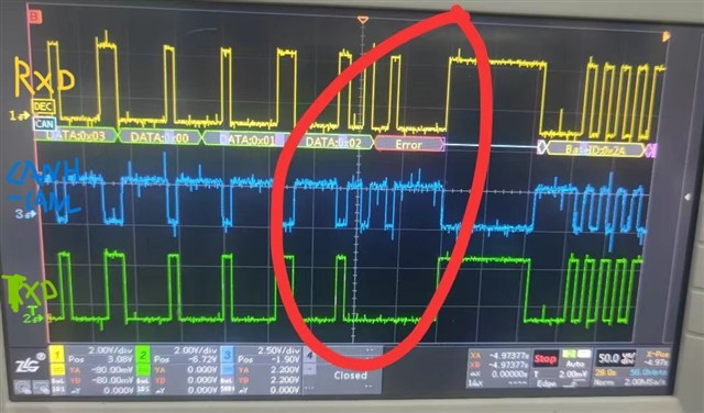
Channel1 is receiver from MCU, channel 2 is tranceiver from MCU. Channel2 Can bus signal was tested through differential probe. There showed abnormal output in red circled sequence. The output bus line supposed to be positive. 
 

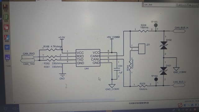
The schematic is showed above.  Can you help take a look in to this ? Thanks a lot!

  • Hello Zoe, 

    Thank you for reaching out.

    It looks like the TXD line goes low and the CAN Bus does not follow (go 'Dominant'). Instead, there is another waveform on the CAN Bus and RXD continues to follow. From the information provided, it looks like there is another node that is communicating on the Bus while U44 is attempting to drive CAN 'Dominant'. However, since U44 should be sending a dominant this should override any other communication on the device.

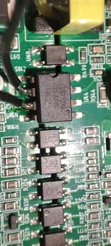
    I noticed that the C54 looks like it is far away from the supply pin. For proper communication, it is essential that this capacitor is placed in the path of VCC2 and less than 2mm away from the supply pins. I would start by checking if the VCC rail is drooping or losing power. This could cause the device to shut off and not drive the bus. 

    To begin debugging please see comments below: 

    1. As stated above, please monitor VCC2 at the pin to ensure the voltage is at the proper level and stable. 
    2. Is the wave form seen above a single event or can it be reliably reproduced?
    3. Is this behavior seen on other devices? 
    4. Does performing replacing the device with a good unit fix the issue (A-B-A swap)? 
    5. Also, I noticed that R344, typically, CAN termination resistance is 120 ohms. If other nodes one the bus have different termination resistances this could cause communication errors. 

    Best,
    Andrew

  • Hi Andrew,

    Thanks for your support! Checked with customer, the system used 3pcs ISO1050 for daisy chain connection. The external circuit was the same but in the middle one doesn't have 100ohom termination resistor. 

    The VCC2 waveform is shown below. 

  • Hello Zoe, 

    It does look like there is substantial ripple on the the VCC2 line. Let me review this information with the team and see if this would cause a missed bit. 

    In the meantime, do you have any feedback on questions #2-5 from my previous post?

    Checked with customer, the system used 3pcs ISO1050 for daisy chain connection. The external circuit was the same but in the middle one doesn't have 100ohom termination resistor. 

    Also, if this statement means that the customer has 3 ISO1050's connected to the same CAN Bus, then it is okay that there is not termination resistor on the middle node. Only the farthest 2 nodes need termination resistors. Is my understanding correct?

    Best,
    Andrew 

  • Hi Zoe,

    I can confirm that the wave form you have previously shown is causing the VCC2 to fall out of regulation. ISO1050's VCC2 must be higher than 4.75V for proper operation, the scope capture shows the voltage droping to 4.1V. The device is likely temporarily losing power and then missing bits as a result. 

    I noticed that the C54 looks like it is far away from the supply pin. For proper communication, it is essential that this capacitor is placed in the path of VCC2 and less than 2mm away from the supply pins. I would start by checking if the VCC rail is drooping or losing power. This could cause the device to shut off and not drive the bus. 

    You could try soldering an additional 0.1uF capacitor directly to the pin to see if this prevents the rail from dropping. 

    I hope this helps. 

    Best,
    Andrew