This thread has been locked.

If you have a related question, please click the "Ask a related question" button in the top right corner. The newly created question will be automatically linked to this question.

ISOUSB111: ISOUSB111 data sheet problem

Part Number: ISOUSB111
Other Parts Discussed in Thread: SN6505A,

Dear TI Engineers,

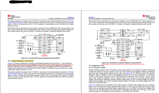
I am looking for a USB bus power isolator and I came across ISOUSB111.  From its data sheet section 10.1.3, it said that Figure 10-3 showed an application for isolating a self-powered peripheral using ISOUSB111.  On the other hand, the title of Figure 10-3 is "isolated bus-powered peripheral using ISOUSB111".

Please clarify.

  • Hi Tim,

    Thank you for sharing this typo in datasheet, appreciate it.
    The word "Self-powered" seems to be mistakenly used in place of "Bus-powered" in the first line of section 10.1.3. I have made a note of this and we will fix this during our next datasheet revision. Thanks again.


    Regards,
    Koteshwar Rao

  • Dear Koteshwar,

    I am going to order the ISOUSB111 EVM.  Here are some of my questions about this kit:

    1. According to the schematic diagram, ISOUSB111 accept 5V from the upstream USB host.  Does ISOUSB111 also output a stabilised 5V to the downstream application circuit?
    2. Is the transformer 110uH WE 750315240 imperative in providing a stabilised 5V to the downstream application circuit?
    3. If I want to provide both stabilised 5V and 3.3V to a downstream application circuit, how shall I set those jumpers on ISOUSB111 EVM board?

    Yours faithfully,
    Timmy

  • Hi Tim,

    Thanks for following up with more questions, please see my inputs below.

    1. ISOUSB111 is only a data isolator and power isolation needs to be done separately. Hence, it doesn't generate 5V by itself to the downstream side.
      1. The EVM for ISOUSB111 does include an external isolated power supply solution based on SN6505A which generates the 5V that can be used to power Side2 of the isolator and the application circuit.
    2. Yes, the transformer along with SN6505A generates 5V that can also be used to power the downstream applcaj circuit.
    3. The EVM only gives out 5V on VBUS2, hence, 3.3V isn't available for other application circuitry.
      1. The 3.3V that is generated by onboard LDO is for powering VCC2 of ISOUSB111 and we do not recommend connecting this to downstream application circuit.

    Let me know if this answers your questions, thanks.


    Regards,
    Koteshwar Rao

  • Hello Koteshwar,

    It sounds like a very versatile USB isolator design.

    I begin to build my BOM of this EVM board.  What I observe is that - TPS76701QD is an older IC and super expensive.  Moreover, its RESET pin is not populated in this EVM and can be ignored.  Now my question is -

    Yours faithfully,
    Timmy

  • Hi Tim,

    I understand your concern on TPS76701QD being an older IC and expensive. Yes, you can choose any LDO that you believe works best for your requirements, this shouldn't have any impact on ISOUSB111 performance.

    TLV76701DGNR seems to be in a different package than TPS76701QD, hence the part replacement might not be straightforward. If you can manage to solder TLV76701 on the EVM somehow, then it should work fine.

    Let me know if you have any other questions, thanks.


    Regards,
    Koteshwar Rao

  • Hi Koteshware,
    Ok nice.

    • Please also upload the BOM of ISOUSB111DWEVM board.

    I have found its board structural diagrams here but no BOM is included.

    https://e2e.ti.com/support/isolation-group/isolation/f/isolation-forum/1087715/isousb111dwevm-isousb111dwevm---pcb-design-board-file-request

    Yours faithfully,
    Timmy

  • Hi Tim,

    You can find BOM of the EVM ISOUSB111DWEVM in its user guide located on the EVM page. I am copying below the EVM page and the direct link to the user guide. Table 7-1 in the user guide is the BOM. Thanks.

    https://www.ti.com/tool/ISOUSB111DWEVM

    ISOUSB111 Full/Low Speed Isolated USB Repeater Evaluation Module


    Regards,
    Koteshwar Rao