


Hello TI-Support Team,
I have a problem with a push-pull-converter setup using SN6505B and Wuerth 760390012.
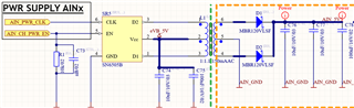
The SN6505B is provided with external clock (500 kHz) and enable signals. The circuit (see picture) is like the datasheet reference implementation.
There are eight channels like this on the PCB. All of them share the clock signal but every channel gets its own enable signal.
This circuit powers an ADC-Channel which pulls around 42mA.
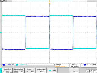
Most of the time everything works as expected, in this case transformer waveform looks like this:
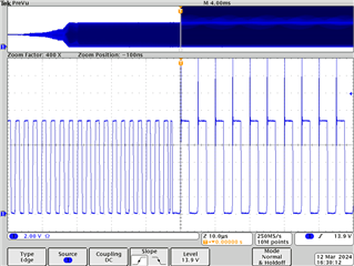
When Enable is pulled low the SN6505 goes into shutdown, as expected. When Enable goes high most of the time the normal operation continues. But in some cases (every 10-20 enable toggles) the SN6505 goes into a weird operation mode and the transformer starts overheating:
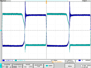
When Enable is pulsed again the SN6505 resumes normal operation (in one rare case it stayed in this op-mode for a second time, but pulsing Enable again resolved it).
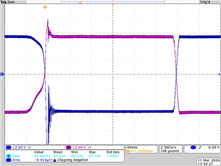
I also captured the startup phase, which shows that this behaviour starts immediately after soft start when the SN6505 switches over from internal clock to external clock (only one transformer winding shown):
When I disable the external clock and the SN6505 runs with its internal clock this behaviour never happens.
Since datasheet and some forum posts say that the schottky diode is a critical part due to reverse current leakage, I switched the diode from MBR120VLSF to SS110LS, but nothing changed.
The strange thing is that out of eight channels on every enable cycle 1-3 channel show this behaviour and the remaining ones are operating normal, but its always different ones. Some are more prone than others, some show this behaviour rarely.
Please tell me if more information or measurements are needed, I will provide them if possible.
Any help is appreciated!
Best regards,
Marcus

