This thread has been locked.

If you have a related question, please click the "Ask a related question" button in the top right corner. The newly created question will be automatically linked to this question.

ISOUSB211: Not working reliably with our designs.

Part Number: ISOUSB211


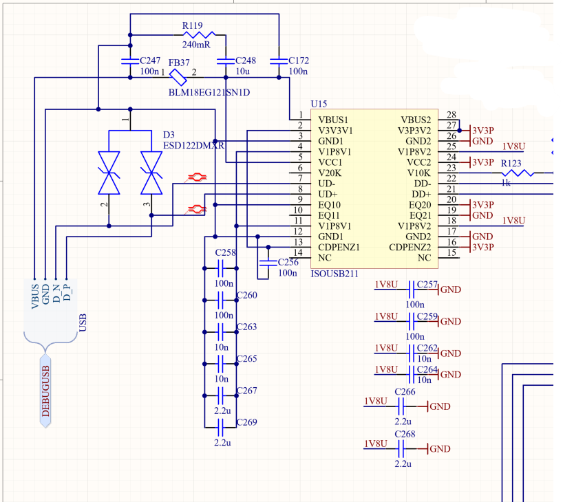
We have implemented a ISOUSB211 in a prototype design.  We are using your reference designs for USB bus powered on the upstream side and 3V3 supply on the downstream side using internal 1V8 regulators.  This design initially worked on 4/5 of our prototypes but after some unrelated rework only 2/5 functioned ever again.  Probing the USB lines on the failing devices it looks like the USB fails in initialization with no chirp responses from upstream.  On at least one of the non working devices the upstream side had a pulse on DP before the DP pullup.  The downstream device is a FTDI FT4232.  Do you know what could be causing this and/or ways to remedy this issue.

  • Hi Brian,

    Welcome to TI E2E forum and thank you for reaching out to us.

    Based on the information you have shared so far, we don't expect the device to have any issues in operating normal. To be able to debug the issue, please share the below information. Thanks.

    1. Please share the schematic so that I can verify if there are any issues or concerns in design.
    2. Can you please share more details about the rework don on the boards? Since some boards stopped working after the rework, it indirectly could have caused an issue including ESD damage to device pin. Hence, please share more details.


    Regards,
    Koteshwar Rao

  • The rework consisted of lifting an output pin of a SN74AHC139DR and bridging the pad to the next output pad over.  The only shared net between the parts is the GND going to the ISOUSB211 GND2.

  • Hello Brian, 

    Please allow us some more time to review the information and respond. We will get back to you on Monday.

    Best,
    Andrew

  • Hi Brian,

    I noticed that I missed to respond back to you on the schematic that you had shared couple weeks ago, sorry about that.
    The schematic looks good and I didn't see any concerns in it.

    Are you still facing the communication issue? If yes, is it possible for you to share the waveform of UD± and DD± at the time of communication issue?


    Regards,
    Koteshwar Rao

  • Sorry for the slow response.  I don't have the part stuff on the non operational boards anymore.  Here are the DD+- at start up on the upstream side of the ISOUSB211:

    After this the D+ pulls down and there is nothing else to see.

  • The 2/5 prototypes that I have working do not have the larger transient at start up.

  • Hi Brian,

    Thank you for your inputs.

    I am not sure what is causing the transient before the D+ pull-up. I don't expect the device to produce such a pulse but need to look more closely to understand this better.

    I understand you have removed the units from the non-operational boards. If you do have any more non-operational units then please do share the test waveform to understand the issue better. While sharing the waveform, please also share the PCB layout so that I can review the same and confirm if there are any concerns with the PCB layout. Thanks.


    Regards,
    Koteshwar Rao