This thread has been locked.

If you have a related question, please click the "Ask a related question" button in the top right corner. The newly created question will be automatically linked to this question.

ISO1641: Hot Plugging Waveforms

Part Number: ISO1641
Other Parts Discussed in Thread: TCA9511A, TCA4307,

Hello, 

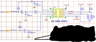
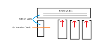
The system I have is a back-plane board where power modules can hot plug into. Below screen shot is triggered on the hot-plug event.

Blue trace is I2C bus side SDA, and yellow trace is SDA micro side. 

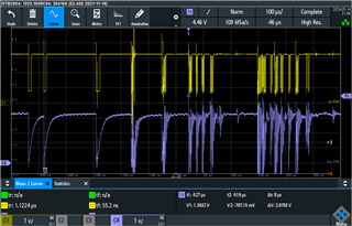
I thought the I2C bus side (side 2) should deal better (not such a large discharge). Is this what should be expected?

The blue trace hit's about - 0.7V, which is outside of the - 0.5V absolute specification; but, would this be classified as an ESD like event? So, can tolerate much higher voltages but much smaller energy.

  • Hello William, 

    Thank you for reaching out. Based on the waveforms provided, we do not expect the device to fail. 

    However, in order to understand if this is expected behavior of the I2C bus, please provide a schematic and a block diagram of what is already plugged in and what device is being plugged into the I2C bus. 

    Best,
    Andrew

  • ESD events are extremely short and thus do not have very much energy. It would be a good idea to add external clamping diodes.

    If you want to avoid disturbing the bus, consider precharging the lines. Also see the TCA9511A/TCA4307.

  • The modules with the red rectangles are the hot-pluggable devices, I only drew 3 but there can be 4. There is a single I2C bus they all connect into on the backplane, which connects to the control card via the ribbon cable. Right after the ribbon cable is the I2C isolating circuit. All modules and control card have same isolating circuit, which is shown below. The bi-directional TVS is being changes to a unidirectional device.

    Why do you think the waveforms look as bad as they are? 

  • I know the ISO1641 pre-charges the VDD, so how would you pre-charge the data lines?

  • Hello William, 

    The use of the bidirectional TVS diodes is a good solution to protect the ISO1641 from the bus transients. The wave forms suggest that the device that is plugging into the bus may not support hot swapping. The other devices plugging into the bus are likely causing this behavior. I am assuming that the red devices in the block diagram are not using other ISO1641. 

    The devices that Clemens mentioned (TCA9511A/TCA4307) are non-isolated I2C buffers designed for hot swapping. It may be necessary to include a buffer like this or use another ISO1641 on each card so that they are hot-swappable and do not disturb the bus.

    Best,
    Andrew

  • Hi Andrew,

    Not sure why you would want to use a bidirectional device on a unipolar signal since the negative swing would get clamped at a much smaller voltage (forward voltage of the device), which in this case is beneficial to the ISO1641 because of the negative swing specs are quite limited.

    Every I2C device plugging into the backplane is using the same circuit I just posted. The circuit I posted doesn't show the isolated power supply, but it's that simple push-pull IC with a wurth XFMR. One suggested in the datasheet.

    So, now knowing every device plugging into the backplane has the ISO1641, how would you start troubleshooting this?

  • Hello William, 

     Sorry for the delay as I continue to look into this issue.

    Best,

    Andrew

  • Hello William, 

    Thank you for your patience. To summarize the issue so far. 

    The blue trace hit's about - 0.7V, which is outside of the - 0.5V absolute specification; but, would this be classified as an ESD like event? So, can tolerate much higher voltages but much smaller energy.

    As long as the -0.7V transient is not happening regularly (for example, on a daily basis), it is not a concern. However, if these transients are expected frequently, then a TVS diode is recommended to protect the device. 

    a unipolar signal since the negative swing would get clamped at a much smaller voltage (forward voltage of the device), which in this case is beneficial to the ISO1641 because of the negative swing specs are quite limited.

    You are correct, the unipolar device would be better suited for this application and provide a smaller clamping range. 

    Also, the 24.5k-ohm pull-up resistance is larger than what is recommended for the device. we recommend using a pull-up resistance between 100-ohm to 6k-ohm. The stronger pull-ups may help mitigate some of the bus noise as well. 

    Best,
    Andrew

  • Hi Andrew,

    Thanks for getting back. The pull-up values unfortunately make sense in our system, because 8 modules can plug in and when you parallel 8 x 24k's it comes to around 1k to 2k effective pull-up resistance. But, it's a good way to check if that is the cause of the problem, so I'll give it go.

    Can we keep this thread open so that I can update as I go along?

  • William, 

    I will have to close the thread for now since there are no pending questions or actions for review on me.

    However, the thread wont lock and will reopen each time a new reply is added on this thread so I will continue to see your updates, or you can create a new post altogether.

    Regardless, I am looking forward to your test results. 

    Best,
    Andrew