This thread has been locked.

If you have a related question, please click the "Ask a related question" button in the top right corner. The newly created question will be automatically linked to this question.

ISOW1412: ISOW1412 / ISOW1044 EMC

Part Number: ISOW1412
Other Parts Discussed in Thread: ISOW1044, , ISOW7741

Tool/software:

Hi, 

we are using the ADM2687 in our design and we see "quite some noise" from the chip in TEM cell near field measurement.

For this reason are very interested in the ISOW1412 and ISOW1044 chips as they are less expensiv and potentially less problematic.

I heard general comment from EMC compliance test house that the TI chips isolation chips cause less clients to fail tests if clients do not follow application notes :-)

In our case it seems like we have done the routing ok, as the measurement is below the limits. However we would like to evaluate the two chips from TI too, as they seem to be available again in quantities.

Analog device recommends Y capacitor and Extending the ground and power planes on an interior layer into the isolation gap of the PCB to form a capacitor. Can you pls give me further design guidance/advice.

I do not see any of this in TI reference design or datasheet? Is there anybody having EMC measurements (emission measurement e.g. CISPR32).

https://www.ti.com/tool/TIDA-010938

https://www.ti.com/tool/ISOW1412DFMEVM

Do you have any CISPR 32 emission measurements of the two chips and detailed info about the layout?

Best Dani
  • Hi Dani,

    Thank you for reaching out and for considering to use ISOW1412 and ISOW1044.

    When the datasheet schematic and PCB layout guidelines are followed, we expect ISOW1412 and ISOW1044 to meet CISPR 32 Class B without the need of Y-Cap or stitching cap (formed using internal PCB layers). Please see below a tech note on ISOW7741 which describes the detailed guidelines for schematic and PCB layout. The devices ISOW7741, ISOW1412 and ISOW1044 use the same DC/DC converter, therefore, all the guidelines provided in the tech note apply all three devices.

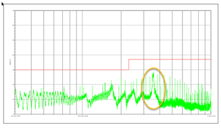
    The report also presents radiated emissions test results. As you can see, the plot is clear of any noise and meets CISPR 32 Class B.

    How to Meet CISPR 32 Radiated Emissions Limits With ISOW7741

    Please make sure the ferrite bead guidelines from tech note are followed. These should be used on both supply and ground lines and to be positioned as suggested to suppress common-mode noise.

    Once you have the schematic and/or PCB layout, please share the files so that I can review and provide feedback. Thanks.


    Regards,
    Koteshwar Rao