This thread has been locked.

If you have a related question, please click the "Ask a related question" button in the top right corner. The newly created question will be automatically linked to this question.

ISO1042-Q1: The correlation between data rates and the length of the CAN bus wires.

Part Number: ISO1042-Q1

Tool/software:

To check the communication success rates of data rates and the length of the CAN bus wires, I had a test.

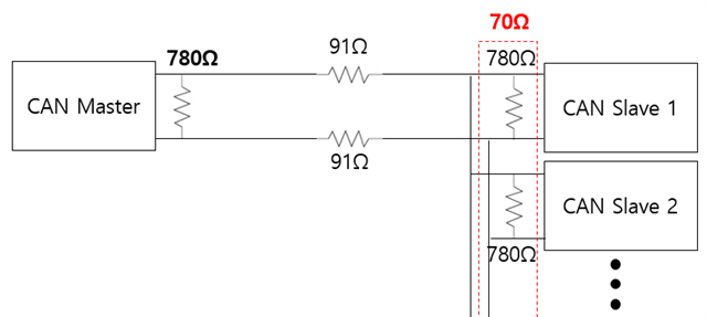
Connect a resistor(To create resistance by the length of the bus wires) between the master board and the slave board, I tested it by changing data rates.

*Test case

1. Data rates : 100kbit/s, 250kbit/s, 500kbit/s, 1Mbit/s

2. Length of can bus wire : 1.08km(91ohm_AWG24)

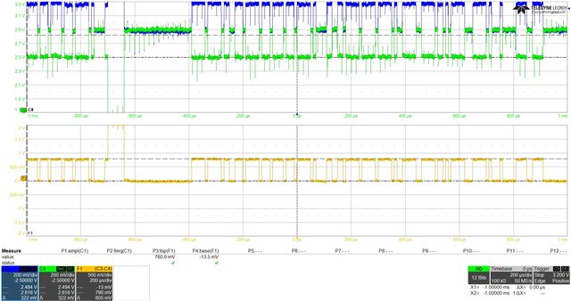
* Result (success rates)

100k 39.6%
250k 89.7%
500k 100%
1M 100%

I think the communication success rates will decrease at higher data rates, I wonder why the opposite results are obtained.

  • Please show an oscilloscope trace (with A − B, if possible) of the failing signal.

    Do you have termination resistors?

  • C1 : Master A, C2 : Master B, C3 : Slave A, C4 : Slave B

    100kbit/s _ 91ohm

    I have termination resistors.

    There is no difference between success(500k, 1M) and failure(100k) waveforms.

  • These waveforms appear to be quite noisy. To check whether this is common-mode noise, tell the oscilloscope to compute CANH − CANL.

    To check whether the receiver works correctly, show both CANH − CANL and RXD.

  • Hello Miho, 

    In addition to Clemens's debug, could you include a capture of the schematic? I suspect there is an issue with the termination resistor's placement and value. I would expect the recessive differential voltage to be smaller for a properly terminated CAN bus.   

    2. Length of can bus wire : 1.08km(91ohm_AWG24)

    Are you testing with 1km of cable? this is way over the recommended bus length for CAN FD. ISO1042-Q1 is designed for a bus length of 40m at 5Mbps speed. 

    Best,
    Andrew

  • THE Yellow waveform is CANH-CANL.

    I can't see noise in this waveform.

  • To improve productivity, 780 ohm terminating resistors were installed on all CAN boards to adjust the resistance between CANH-CANL lines to 60 ohms.

    So, On the master's side terminating resistor is 780ohm, slave's side  terminating resistor is 70ohm.

    Could this be a problem?

  • The yellow waveform shows that the noise was common-mode noise, which is harmless for differential signals.

    The termination resistor must match the characteristic impedance of the cable, which is usually 120 Ω. CAN drivers are designed for a load of 60 Ω, so a CAN bus should have exactly two termination resistors, at the two ends of the bus.

    The differential bus voltage must be at least 1.5 V. It's about 0.8 V in your case, so receivers might have problems detecting it. Your cable is too long (i.e., 91 Ω is too high).

    One method to increase the voltage at the receiver is AC termination, but this works only at low speeds.