This thread has been locked.

If you have a related question, please click the "Ask a related question" button in the top right corner. The newly created question will be automatically linked to this question.

ISO1228: What is the purpose of Rpar and can it be omitted?

Part Number: ISO1228

Tool/software:

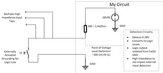
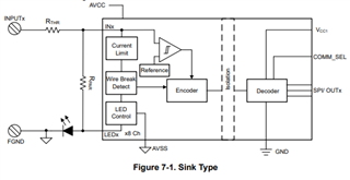
I am designing a circuit with a series of relatively strong pullups to 28V that can be FET-switched to ground, and I need to detect logic levels between 28V and ~0V through isolation (this is not a IEC 61131 application), and the ISO1228 looks like a promising fit.  I don't need LEDs or wire break detection and plan to use parallel outputs not SPI.  However I also need to limit the current draw of the inputs to the ISO1228 circuit as well as maximize the input impedance of the input circuit, and the sneak path of the recommended 13kOhms Rpar is making that difficult.  What is the purpose of the Rpar resistor and can it be omitted?  If I ground the LED pins and select appropriate values of Rthr and Rlim can I get the effective input impedance of my circuit inputs into the 100's of Kohms?

  • Hello Kirk, 

    Thank you for your interest in ISO1228. I understand that you are trying to achieve 28V inputs with current limit and do not need to comply with the IEC spec. Without Rpar, the device will be functional, however there will be no current limit. The LED pins can also be grounded without any issues since wire break detection is not needed.

    Based on the datasheet Rilim is only recommended to be between 0 and 1k-ohms. Permissible RTHR resistors are only in the range of 180Ω to 2.4kΩ (8.2.1 Sinking Type Digital Inputs).

    What is the reason that the input impedance needs to be in the 100k-ohm's range?

    Best,
    Andrew

  • I cannot guarantee that my circuit will be the only "input" hanging off of this signal, so it feels like in a high/ON state this circuit will pull the voltage low, meaning other high impedance inputs on this signal may see a value between 28V and something much lower, 10-15V, which would be inappropriate for my system.  If the signal is pulled up to 28V with an external 10K resistance at the source, multiple high impedance inputs will still read that as very high, >26V or so.  The Rpar of 13kOhm will pull that value down to 28V x 13/23 = 15.8V, which may be read as an indeterminate value by other high impedance inputs.  I can solve this easily with a high voltage comparator, but I have lots of signals and limited board space so the ISO1228 fitting eight channels of inputs plus isolation in a single chip is awesome if I can figure out how to make it work.

    How does Rpar impact current limitation if the path is completely external to the chip?

  • Hello Kirk,

    Thanks for your follow up. Please note that we have a holiday on Monday which will delay our response. Andrew should be able to get back to you on Tuesday.

    Best,
    Michael

  • Hello Krik, 

    I am not sure I understand what your application is or what you are trying to achieve. What is the input signal? And could you please provide an application diagram? 

    Best,
    Andrew

  • I have multiple signals where the signal in question is pulled up to 28V through varying resistances ranging from 300 ohms to 5.6Kohms depending on the needs of that signal.  An external switch or FET can either ground that signal or be kept open allowing the resistor to pull that wire up to 28V.  I need my circuit to be able to connect to this wire and convert the state of this signal from 0-28V to a logic level signal that is isolated from the ground reference of the 28V signal,  The ISO1228 seems very capable of doing this, however I have one or more additional external taps to this signal that will also be independently detecting this 0-28V level that are not under my control.  These external inputs will be high impedance so will not significantly impact the voltage compared to the strong 300-5600 ohm pullup on my circuit, however the seemingly maximum input impedance of the ISO1228 circuit will be 14kOhm (1k Rthr plus 13k Rpar), which will drag down the voltage of my test point to between 27.5V with a 300ohm pullup to 20V with a 5600 ohm pullup.  While 27.5V will be OK, the 20V will be in an undefined region as my Vhigh for the signal is >27V and the Vlow is <2V.  I need to understand how I can get my ISO1228 circuit input impedance up much higher than 14kOhm, preferably greater than 190Kohm at a minimum.

  • Hello Kirk, 

    Thank you for the additional details. Could the resistor in your circuit be 300-ohms? If yes, then ISO1228 will work with below circuit and RTHR = 1k-ohm and Rpar = 13k-ohm. Connect the INPUTx terminal to the "point of level detection node" and FGND to GND.

    If the resistor in your circuit needs to be 5.6k-ohms, then this will not work. 

    Alternatively, you could use a digital isolator with a resistor divider at the input. However, this would not be as robust. 

  • Thank you, unfortunately the range of pullup resistor is variable and out of my control, so I must design for the whole range.  Looks like the ISO1228 isn't a fit here, but it sounds like an ideal part for its intended purpose.