This thread has been locked.

If you have a related question, please click the "Ask a related question" button in the top right corner. The newly created question will be automatically linked to this question.

ISO1228: Device query

Part Number: ISO1228

Tool/software:

Hi Team,

Customer is using ISO1228DFBR for 24V Digital Input. During testing process, customer is facing below issue:

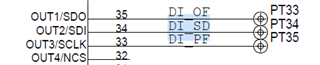
When 24V in given from J9 connector in pins 2, 3 & 4 (DIN1_OF, DIN2_SD, DIN3_PF) – Expected output of DI_OF, DI_SD, DI_PF is 3.3V.

The following data is measured before flashing the code. It is observed that when Logic is 0, DI_OF is at 2.01V instead of 0V.


Schematic.docx

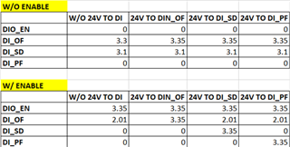
After flashing the code, the DI_OF line is not receiving 3.3V, instead only 1.35-1.5V is received.

This is the case with any new board or old board. 

 The line of input to 24V, there’s a drop but, at least 22V is received at the input after protection. DIO_EN is directly powered by 3.3V by default. 

Customer also tried to provide the first input (DIN_OF) to the 8th channel of the same IC, But no output is received on the other side.

Can you let me know, if this might be caused because of any issue with the IC?

Regards, Shinu.

  • Hello Shinu,

    Thank you for your explanation. 

    When DIO_EN (Pin OUT_EN) is 0V the ISO1228 has tristate outputs. The first table (w/o enable) still shows voltage on some of the DI_PF, SD, and OF lines. When the OUT_EN pin is enabled the voltages on the DI lines go to an intermittent value.

    I suspect that there is some bus contention between the ISO1228 and the MCU since the logic outputs of the ISO1228 is at an intermittent value. I would start by making sure that the MCU pins are not driving the DI_PF, SD, OF lines.  If possible, test the operation of the ISO1228 by itself with the MCU disconnected. 

    Best,
    Andrew

  • Hi Andrew,

    Thank you for your input.

    As suggested, have disconnected the controller from the IC, and now when DIO_EN is low/floating, the inputs are at 0V.

    Now, the new issue is when 24V is powered to DIN_OF, the output is still 0V (when DIO_EN is pulled high).

    But, when the remaining two inputs (DIN_SD/DIN_PF) are initially powered in any order (in live condition), and then the DIN_OF is powered, in that case DI_OF is 3.3V.

    Please Note that this occurs only when done in LIVE CONDITION. When powered on/off individually, still DI_OF has no output (0V).

    Updated Results

    We're simultaneously checking the PCB for any issues, but I'd like to know if you have suggestion as to check if the IC has something to do with this.

    Thanks, Shwetha.

  • Hello Shwetha, 

    I am glad to see there was some improvement after the bus contention was removed (the MCU output and the ISO1228 output were connected together). 

    But, when the remaining two inputs (DIN_SD/DIN_PF) are initially powered in any order (in live condition), and then the DIN_OF is powered, in that case DI_OF is 3.3V.

    Please Note that this occurs only when done in LIVE CONDITION. When powered on/off individually, still DI_OF has no output (0V).

    Each output should match the input when the channel is independently powered on/off of the other channels. It is possible that the pin is damaged after the bus contention. I would suggest replacing the ISO1228 with a new device and seeing if the issue persists. 

    Best,
    Andrew 

  • Hi Andrew,

    Yes, we've already tried replacing the IC with new sample and disconnected the MCU as well. In that case as well, we're seeing the same issue.

    Thanks, Shwetha

  • Hi Shwetha, 

    I suspect that there is a higher-level issue in the PCB since you have swapped the IC an disconnected the MCU to test the ISO1228 independently. 

    The ISO1228 will consider an input in the 'ON' state when both the voltage and current thresholds are met. Is it possible that the DI_OF does not get enough input power unless the other two inputs are on? 

    Best,
    Andrew

  • Hello Shwetha, 

    Could you also try disconnecting the remaining INx pins from GND and let them float?

  • Hi Andrew, 

    Tried disconnecting remaining INx pins. No change in result.

    I would also like to know, if any pulldown resistor is required at the output side?

    In our schematic, we've directly connected the OUT1 to controller.

    Thanks, Shwetha

  • Hello Shwetha, 

    No pull-down resistors are needed, and the output pins can be connected directly to the MCU inputs. For further debug, please attach scope capture of the input and output waveform of a working channel and a not working channel.

    Best,
    Andrew

  • Hello Shwetha,

    I have reviewed the post again with a colleague this morning and I would like to back track a little to make sure some important points have been covered.

    To start, the schematic looks okay, and from the schematic alone I do not expect any issues. My primary observation from the original post is with regards to the table "w/o enable" (I assume this is when OUT_EN = GND). In this state I would expect the ISO1228's output pins (pins28-35) to be 0V since there are no pull-up resistors in the schematic. This behavior would suggest that something is unusual.

    Troubleshooting this would be difficult on the PCB with the MCU. As discussed previously, the best method to continue the debug would be necessary to test the device independently and disconnect the MCU electrically on the PCB.

    On the PCB, I am assuming the MCU is connect physically over traces. Please confirm that the traces are cut or the MCU is removed to test the ISO1228 alone (and the MCU is not just powered down).

    Otherwise, you could test on the ISO1228 EVM to confirm the device's functionality. The device has been verified on the EVM over various tests. 

    Best,
    Andrew