Tool/software:
Dear Specialists,
My customer is encountering the problem regarding ISO1432.
I would be grateful if you could advise.
---
We are using a half-duplex connection between ISO1432B and a connector in our equipment.
Regardless of whether an external device is connected or not, it continues to send commands to external devices at regular intervals.
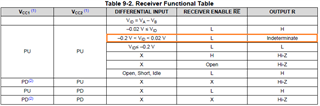
We have found that the fail-safe function does not work properly even when nothing is connected to the connector, and we are investigating the cause.
With this background in mind, I have three questions.
Q1. Will the fail-safe function not work when ISO1432B is connected in half-duplex?
Q2. There is a half-duplex product in the same series called ISO1430B.
Will the fail-safe function function more correctly with this product?
Q3. Is it advisable to attach an external resistor to ensure that the fail-safe function works properly?
---
I appreciate your great help in advance.
Best regards,
Shinichi