This thread has been locked.

If you have a related question, please click the "Ask a related question" button in the top right corner. The newly created question will be automatically linked to this question.

SN6507: Gate Driver Bias Power

Part Number: SN6507
Other Parts Discussed in Thread: POWERSTAGE-DESIGNER

Tool/software:

Customer would like to do the bias power of gate driver for AC inverter. Is there ref. design similar to below condition?

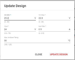
Input Voltage: 24V+/-5%

Isolated Output Voltage: 24V (x3)

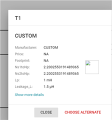
Remark: There're three 24V ISO outputs for IGBT's bias power. The total output power is about 5W. Could SN6507 using only one transformer to do so? thanks.  

Regards

Brian

  • Hello Brian, 

    Good question. SN6507 can handle a continuous current of 0.5A on the switches. At a 24V output this would bring total maximum output power to ~12W (24V*0.5A) with an ideal transformer. The solution should be able to support three devices as long as the total current need is below 0.5A.

    Best,
    Andrew

  • Thanks Andrew. 

    We'd like to know if one SN6507 is able to drive the multiple winding for +24V x3? if so, could you offer the ref. design! Very thanks. 

    Regards

    Brian 

  • Hello Brian, 

    SN6507 would be able to drive multiple transformers windings as long as the selected transformer has a VT-product higher than the minimum product calculated in the transformer selection portion of the datasheet. 

    Currently we do not have a reference design for an application like this. 

    Best,
    Andrew

  • Thanks Andrew. I mean that the one device to drive one transformer with multiple windings for multiple outputs. Is that possible to do?

    Customer can just accept only one transformer to do so as the cost and system size considerations! Very Thanks. 

    Regards

    Brian

  • Yes, that is possible. If you have a transformer datasheet, then please send it and I can review. 

  • Hello Andrew,

    Customer would like to implement the 24Vin to 24V_1, 24V_2 and 24V_3 for bias power of gate driver. however, we're confused how to do the inductance calculation for push pull? in the d/s, it is just mentioned the V-T value, how to design the transformer with this value? 

    Regards

    Brian

  • One more inputs, here is the calculation result from RD. please check if it's ok or not? thanks. 

    24Vin to 24Vout/12W,max

    Step. 1

    Define switching Freq.


    FSW

    1000

    (kHz)


    RCLK

    9.53

    (kohm)

    Step. 2

    Set the input UVLO


    VIN_UVLO

    9

    (V)


    RENT

    10

    (kohm)


    RENB

    2

    (kohm)

    Step. 3

    Set the Current limt and soft-start time


    ILIM

    0.5

    (A)


    RILIM

    49.9

    (kohm)

    Step. 4

    Set Duty cycle


    D_typ

    0.25


    Vcc

    24

    (V)


    RDC

    50.55488

    (kohm)

    Step. 5

    Transformer selection - Vtmin


    Vtmin

    8

    Vus


    Vcc

    24

    (V)

    Step. 6

    Transformer selection - Turn ratio


    VF_max

    0.5

    (V)


    VDO_max

    0.7

    (V)


    VO_max

    24

    (V)


    VIN_typ

    24

    (V)


    RDS_max

    1

    (ohm)


    ID_max

    0.5

    (A)


    Nmin

    2.20902128

    Np/Ns

  • Hello Brian, 

    This is a lot of good information. Please allow me a day to go through it and I will get back to you tomorrow.

  • Thanks. If any update, please let me know asap. thanks. 

  • Hello Brian, 

    Thank you for your patience. The values look good, and I don't expect any issues. Please see my comments below. 

    • The CLK pin can be shorted to GND is the clock frequency is default (1MHz). 
    • I understand the goal of the application is 24Vin to 24Vout/12W,max. If you are planning to use duty cycle control, then please also calculate the inductor value using equation 2 in Inductor Selection. 
    • The transformer equations also looks good. 

    Also, I would like to mention that Power Designer has a SN6507 module that can be used to calculate a lot of these values and provide a starting schematic. 

    Best,
    Andrew

  • Thanks. Regarding to the PUSH-PULL There are a few more questions I would like to ask for your help

    1..Why do I calculate the number of turns on my transformer with the Power stage design tool that is so much worse than the formula given in the SN6507 specification? Is it because of the control method? (The specification is open-loop duty control, and the default control mode for the Tool is?)

    2.transformer excitation current Magnetization current has a recommended% number?

    Step. 1

    Define switching Freq.


    FSW

    1000

    (kHz)


    RCLK

    9.53

    (kohm)

    Step. 2

    Set the input UVLO


    VIN_UVLO

    9

    (V)


    RENT

    10

    (kohm)


    RENB

    2

    (kohm)

    Step. 3

    Set the Current limt and soft-start time


    ILIM

    0.5

    (A)


    RILIM

    49.9

    (kohm)

    Step. 4

    Set Duty cycle


    D_typ

    0.25


    Vcc

    24

    (V)


    RDC

    50.55488

    (kohm)

    Step. 5

    Transformer selection - Vtmin


    Vtmin

    8

    Vus


    Vcc

    24

    (V)

    Step. 6

    Transformer selection - Turn ratio


    VF_max

    0.5

    (V)


    VDO_max

    0.7

    (V)


    VO_max

    24

    (V)


    VIN_typ

    24

    (V)


    RDS_max

    1

    (ohm)


    ID_max

    0.5

    (A)


    Nmin

    2.20902128

    Np/Ns


    Reards

    Brian

  • Hello Brian, 

    Please, can you let me know which equation you are using in the datasheet to calculate the turns ration of the transformer? As well as the value in your tool? 

    The transformer turns ratio calculated by the tool that I have access to comes out fairly close to your 2.209 number (online WEBENCH Power Designer).

    • Inputs
    • Calculated Transformer Specs

  • Hello Andrew, 

    1. Customer is using below equation for Nmin that is specified in d/s.

    2. Please find the below customer conditions. It looks the below result is different to what Webench calculated? 

    Webench: turn ratio: 2.20

    POWERSTAGE-DESIGNER:0.74

    Which one is correct one?


    Regards

    Brian

  • I would recommend following the datasheet equation since it lines up closer with the WEBENCH power designer. Please see the below solution.

    Using the numbers provided in step 6 and 24V Vin +5% (or 25.2V) for Vmax. 

    • Nmin = 1.03*((0.5+0.7+25.2)/(24-1*0.5))*(1/(2*0.25)) = 2.3

    If you use 24.0V for VO-max then the equation returns Nmin = 2.209 which would be less accurate since the solution does not include the expected supply variation. However, it matches the WEBENCH turns ratio.

    I cannot comment on how the POWERSTAGE-DESIGNER is calculating 0.74. However, I suspect it is not accounting for the duty cycle control feature since it is not a typical feature in push-pull converters. 

    Best,
    Andrew

  • Hello Andrew,

    Turn ratio is ok, how about the calculated inductance value?

    Regards

    Brian

  • Hello Brian,

    The Lout inductor can be calculated according to equation 2 

    Assuming an I_load.min = 0.2A, WEBENCH calculates 18uH. 

    Best,
    Andrew