


Tool/software:
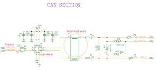
Designing a custom PCB with CAN section. Attached is the design schematics. Please validate and suggest any changes.
Tool/software:
Designing a custom PCB with CAN section. Attached is the design schematics. Please validate and suggest any changes.
