This thread has been locked.

If you have a related question, please click the "Ask a related question" button in the top right corner. The newly created question will be automatically linked to this question.

ISOW1432: Termination Resistor 120E Heating

Part Number: ISOW1432

Tool/software:

Hi,

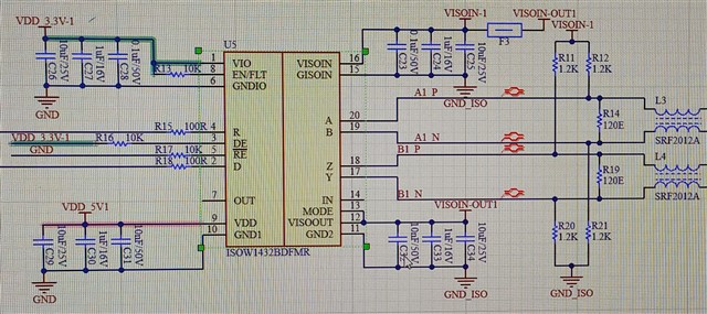
I am using ISOW1432 RS422 Transceiver, Attached the circuit diagram of it.

When i am trying to power it up, Transceiver and Termination resistor 120E at Y,Z line is getting hot.

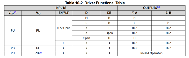
This is because of default line state (Y - High & Z - LOW) as per the input configuration set (DE - High & RE - LOW) (D - Float & R - Float)

I just want to clear, Is it the right way to be in standby mode or we have to control the DE pin to make it LOW when in standby mode 

So that Y,Z will be in high impedance and there will be no un-necessary current flowing through the termination resistor.

Thanks  

  • DE enables the driver. To disable the driver, you have to pull DE low.

    R19 can be removed; for a unidirectional point-to-point connection, termination is needed only at the receiver's end of the cable.

    The fail-safe resistors (R11/R12/R20/R21) are needed only if there is a receiver without failsafe on the bus (the ISOW1432 does have a failsave receiver), or if you want to increase the fail-safe noise margin. In any case, you need only one set of fail-safe resistors on a bus, usually at the receiver's end.

  • Hi Clemens,

    Thanks for the prompt reply.

    After removing the Termination resistor it will solve the heating issue.

    As i have no provision to control the DE and RE pin, It is hard set through the resistors (R16, R17)

    Is it ok to be in this state or we must need to control the DE when we are not transmitting.

    Thanks 

  • When DE is high, then the Y/Z outputs will be active. If the output is connected to a receiver with a termination resistor, then the current through the bus must be supplied by the ISOW1432. One 120 Ω resistor consumes less current than two 120 Ω resistors in parallel; if you want to avoid that current, you'd have to pull DE low. And even when DE is low, the current through the fail-safe resistors still flows.

  • Hi Subash,

    Everything that Clemens has shared is correct.
    In summary, you would have to control DE pin HIGH or LOW based on whether you are transmitting data or in idle. Not doing so can lead to high current consumption. This is how the RS-485/RS-422 bus is implemented.

    Let me know if you have any other questions, thanks.


    Regards,
    Koteshwar Rao

  • Hi Koteshwar,

    Heating Issue is resolved.

    Now i am able to transmit and receive data by doing looping of YZ line with AB line.

    But when i am connecting it with a device which is transmitting a data at 50Hz rate at 115200 baud on RS422 Receiving node (RS422 Driver Output is Floating)

    I am getting some corrupted data packed at UART.

    Same device is working fine with a (RS422 to TTL Converter Module).

  • Please show an oscilloscope trace of the differential bus signal (A − B or Y − Z) and the received signal.

  • Hi Subash,

    I understand that you have connected your product with another RS-422 node.
    Can you please confirm that only one of them is transmitting and the other is receiving during the test?
    Can you please also confirm that the driver (DE) of only one device enabled and not both?

    If both drivers are enabled by pulling them up to VDD, then the data on bus can be corrupted. Please check this and confirm.
    Please also share waveform so that we can review and confirm, thanks.


    Regards,
    Koteshwar Rao