This thread has been locked.

If you have a related question, please click the "Ask a related question" button in the top right corner. The newly created question will be automatically linked to this question.

ISO1211: ESD and fast transient / burst problems with ISO1211

Part Number: ISO1211

Tool/software:

Dear sir or madam

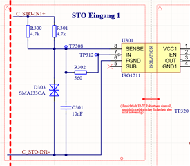
In an STO application (safe torque off) we implemented two ISO1211 for the input signals. As the maximum length of the STO input cables are limitted to < 30m withstanding of surge tests is not required. Therefore we build up the input circuit with a 2.35k resistor for the threshold definition, a 560R resitistor for current definition, a 10nF capacitor for noise reduction and a TVS diode (33V Breakdown Voltage) for overvoltage / transient protection according information from the datasheet. (datasheet figure 22) According the informaiton given in the datasheet the circuit should withstand fast transient pulses as well as ESD pulses. Unfortunately, ESD pulses destroyed the input of the ISO1211 isolators.

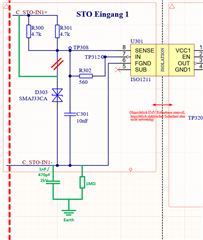
According the information in the datasheet capacitors from the negativ signal input line to earth would help to withstand fast transient pulses, ESD pulses and surges (recommende for withstanding of surge pulses, even surge tests are not required for this design) according figure 23 in the datasheet.

Is there any experience or assumptions why the current design got destroyed by ESD pulses of an amplitude of 2kV?

Are there any sticking points / good tips and tricks on how the circuit could be made more resistant regarding fast transient pulses and ESD pulses?

Would the implementation of capacitors between the negative signal lines and earth be an option? If so, what are the advanteges and disadvanteges of this?

Many thanks in advance for your feedback.

Best regards Iwan Briker

  • Hello Iwan, 

    Thank you for reaching out. I understand that you revied the information in Section 9.2.1.2.5 Surge, ESD, and EFT Tests of the datasheet and are seeing the inputs fail at ESD pulses less than what is shown in the datasheet (2kV). I would first start by checking the surge rating on the input resistors and the TVS diode. 

    • Please share the part number for the TVS diode. 
    • What was the standard and level of ESD that you were testing?
    • Could you please share a schematic? 

    Additional capacitance in parallel with Cin will likely have small benefit. However, it could slow down or limit the data rate at the input. 

    Best,
    Andrew

  • Hello Andrew

    Some additional information regarding the ISO1211 design.

    The package for the resistor R300 and R301 is 0805, which should be suitable for withstanding ESD and EFT pulses. (Withstanding of surge pulses is not required due to limitation of the cable length.)

    The package of the TVS diode is SMA. (Approved components: SMAJ33CA-H Bourns, Inc, SMAJ33CA Taiwan Semiconductor Co., Ltd., SMAJ33CA-TR STMicroelectronics N.V., SMAJ33CA Littelfuse, Inc. and SMAJ33CA-TP Micro Commercial Components Corp.)

    The ESD pulses (contact discharge) that destroyed the ISO1211, were applied according EN 61000-4-2. ESD pulses with an amplitude of +2kV and +4kV have led to a significant shift in the input threshold levels, ESD pulses with +6kV led to the destruction of the ISO1211. According the information in the datasheet that should not happen.

    To increase the robustness of the desgin regarding ESD pulses and EFT I planned:

    - to connect the already implemented TVS diode D303 directly between STO+ and STO- (green path in the upper left corner of the picture below.)

    - to implement a 1nF or 470pF capacitor and a 1MOhm resistor from the negative input (STO-) to earth potential. (green components)

    Questions:

    - Is the planned redesign a good strategy?

    - According the informaiton in the datasheet a capacitance to earth should not exceed a value of 500pF for optimized surge behavior. Due the design does not have to fulfill surge tests higher capacitance values were allowed, isnt' it? Wehere are the limits of the capacitance value respectively what is the impact of earth capacitors > 500pF.

    - In case that an earth capactitor must be < 500pf an additional TVS diode in parallel with the earth capacitor and the resistor is necessary respectively needs to be implemented.

    Best regards

       Iwan

  • Hello Iwan,

    The peak power capability of the resistors R300 and R301 need to be rated for several amps of current. It is recommended to use the pulse-proof resistors shown in the datasheet. are in the amp of current range. 

    We agree that the planned redesign is a good strategy. The resistances may be slowing down the TVS response time the diode should be placed as close as possible to the connector. I would recommend testing without the additional RC to earth ground first and adding them in later if further improvements are needed.

    Best,
    Andrew

  • Hello Andrew

    Thanks al lot for the feedback. I will check the resistor topic and may replace the standard resistors with puls proofen types.

    Do you have information regarding the value of the earth capacitor? What will happen if I implement a 2.2nF capacitor regarding signal performance as well a EMC behavior? (the current design doesn't requiires highspeed signal transition resp. the toggeling of the signal is below 1kHz.

    Best regards

        Iwan

  • Hello Iwan, 

    We haven't tested larger capacitors on the path to earth ground. Generally, it would help improve EMC and not affect the data rate.  

    Best,
    Andrew