ISOW1432: Isolated RS-485/RS-422---ISOW1432 Regarding Half-duplex mode of operation

Part Number: ISOW1432

Tool/software:

Hello,

We have few concerns on the ISOW1432 part design.Can someone clarify below questions.

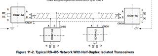
1. To change to half duplex mode we need to short  Driver outputs Y and Z are shorted to A and B respectively and the split termination is provided between A and B but in EVB board the Split termination is provided a between Y and Z. Please clarify which one to follow.
2. How to change to RS422 transceiver mode.

3. Does ESD diodes required for this isolated transceiver module.

4. GND2 reference is required for differential pair if we route that in top and bottom layers.

5 Common mode choke is necessary , if so suggest part numbers (not available in EVB)

6. Suggestions for trace width of A/B/Y/Z.

7. Minimum stub length in PCB side.

  • Hi Divya,

    Thank you for reaching out, please see my inputs below.

    1. Your understanding of converting full-duplex to half-duplex is correct.
      1. The ISOW1432DFMEVM includes both a single resistor termination and split termination to demonstrate that termination can be done two ways.
      2. There is no relevance of positioning these terminations on driver and receiver, they were arbitrarily placed on them.
      3. Please feel free to choose split-termination for your application.
    2. RS-485 transceiver electrical specifications are already compatible to RS-422 and do not require any design change. ISOW1432 is going to work fine in RS-422 without requiring any additional changes. I am listing below the key differences in RS-422 and RS-485 and copying a link to an application that provides more details about the differences between them.
      1. RS-422 and RS-485 Standards Overview and System Configurations
    3. This depends on whether you require EMC protection on the bus. For most applications, use of TVS or other protection devices is required to meet end-equipment EMC requirements like ESD, EFT and Surge.
    4. I didn't quite understand your question. If you meant to ask if you should use GND2 (pin 11) or GISOIN (pin 15) for reference the differential pair, please use GISOIN.
      1. Please refer to the example PCB layout provided in ISOW1432 datasheet.
    5. Common-mode choke (CMC) on RS-485 bus is typically not required, therefore, I do not have any recommendations to suggest.
    6. The current on RS-485 bus is typically not very high (<100mA), therefore, trace width of 10mil (supports 1A) is usually sufficient. Choosing higher widths will keep the trace resistance to minimal.
    7. The stub length should be kept as minimal as possible to minimize reflections. Typically, most designers position the RS-485 transceivers to the edge of PCB and that works best. For a calculate upper limit value for stub length, please refer the below design guide.
      1. The RS-485 Design Guide


    Regards,
    Koteshwar Rao