Other Parts Discussed in Thread: ISOW7721
Tool/software:
Hi Ti team,
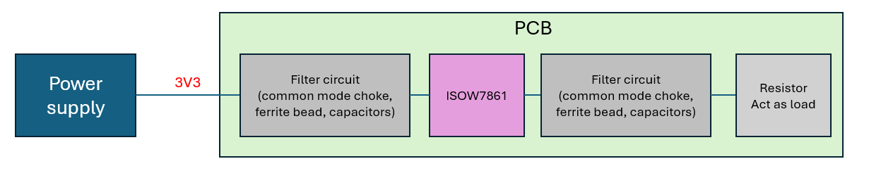
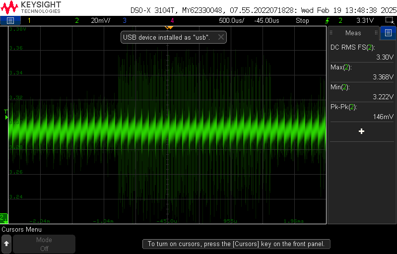
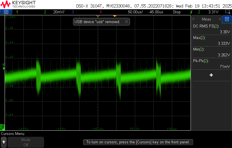
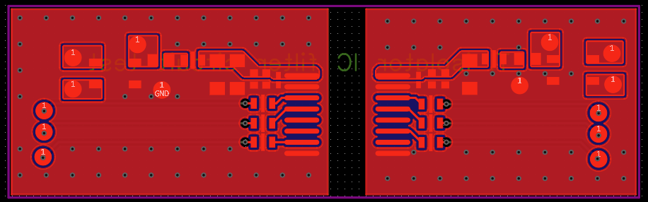
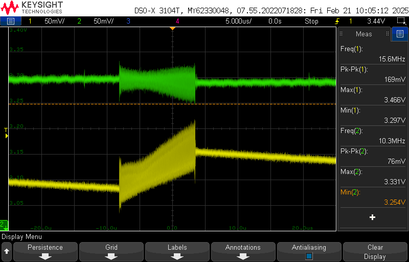
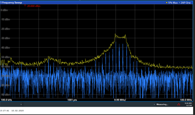
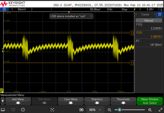
The customer has the following ripple and radiation application problems of ISOW7821, and needs to give some suggestions
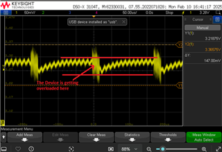
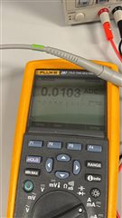
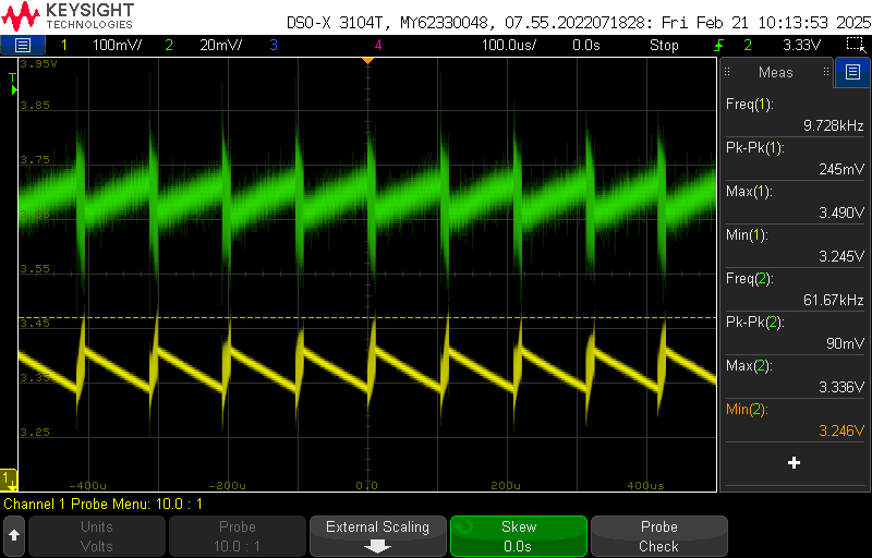
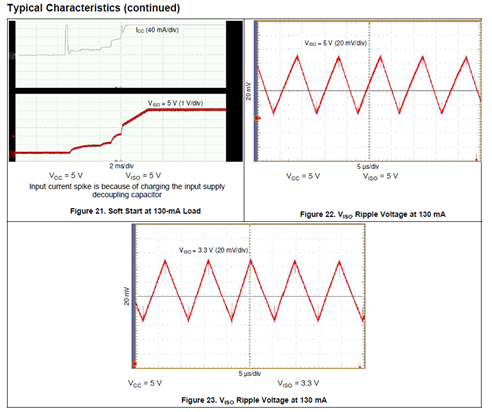
From the IC spec sheet, there are noise ripple generated from the IC power buses and we now face the same issue and need FAE support.
How can we eliminate the voltage ripples and reduce the noise emissions?


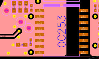
 L2
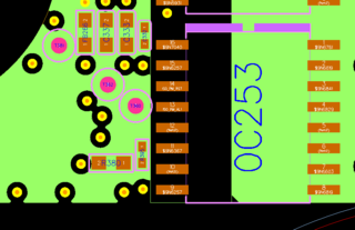
L2  L3
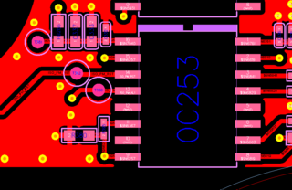
L3  L4
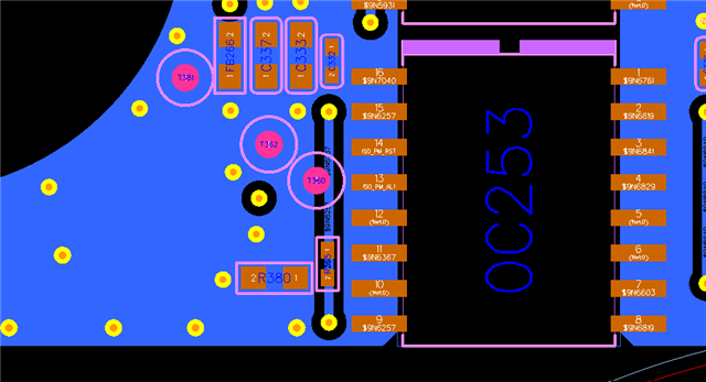
L4