This thread has been locked.

If you have a related question, please click the "Ask a related question" button in the top right corner. The newly created question will be automatically linked to this question.

ISO1452: ISO1452 outputs not complimentary

Part Number: ISO1452
Other Parts Discussed in Thread: ISO1450

Tool/software:

I’m using the ISO1452DW in a new design and having a strange issue; perhaps you can help me troubleshoot it.  First, the schematic:

 You can see that the 1.8V supply is powering the “inside” of the transceiver, and I have a separate, isolated 5V supply powering the outside.  (actually it's 4.96V but close enough.)


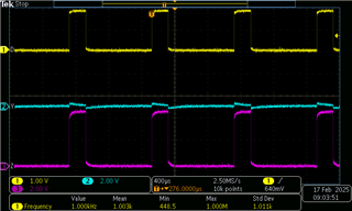
I’m testing the 1452 driver side right now, which means I have pin 5 pulled high to 1.8V via a 100k resistor, as you can see in the lower left of the schematic screenshot. I’m feeding a 1kHz, 1.8V pulse train to pin 6, the driver input, and I expect to see differential outputs on pins 11 and 12.  However, instead of this, I see two outputs that match the input phase exactly; there seems to be no complimentary output.  The voltages seem reasonable, but both output pins are both the same phase.  See scope plot below:


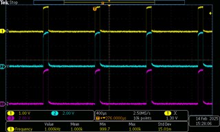
Any ideas what’s happening here?

 Thanks, and have a great weekend!

Geoff (DTS)

Seal Beach, Ca

  • I'd guess that the inverting output (Z) or its solder connection is broken, and that the line is pulled to Y through the termination resistor. Check if the line is floating when you remove the resistor.

    (For a unidirectional connection, a termination resistor is not needed on the driver end of the cable. And 75 Ω is an unusual value; with the termination at the receiver, the load would be too high.)

  • Hi Clemens, thank you for the reply.  I removed the termination resistors on the outbound direction, as well as the TVS, just for good measure.  

    I am probing with my scope directly on the pads to which the Y and Z pins are soldered, and this is what I see. 

    The voltage on the DE pin (driver enable?) is only 1.56V.  perhaps this part needs a stronger pullup resistor?  I am not driving the pin, just relying on the pullup to enable the driver.

    Thanks

    Geoff

  • Ok, I just shorted the DE pin to 1.8V directly, to check, and I still see the same thing on the output: the in phase outputs, with one side greatly reduced in amplitude (looks like leakage to my eyes).

    So it's not the enable pin.  

  • Mystery Solved.  Our CM installed the wrong parts (ISO1450 instead if the ISO1452)

    Thank you Clemens