This thread has been locked.

If you have a related question, please click the "Ask a related question" button in the top right corner. The newly created question will be automatically linked to this question.

ISO1050: Chip application problem

Part Number: ISO1050

Tool/software:

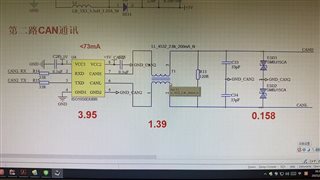
This road CAN is the scheme of the above schematic diagram, R13 has been removed, please help to check whether the schematic diagram is correct?

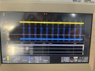
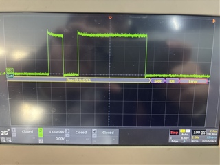
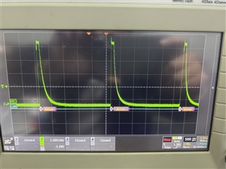
I have 1 other CAN, if the two CAN parallel, matching a 120 ohm resistor, the waveform is overload. No resistance is directly abnormal wrong waveform, what should be the problem?

  • Hello Tonyx, 

    Thank you for reaching out. The CAN waveform will have a slow decay (as shown above) if there are no 120-ohm termination resistances installed. Please make sure the R13 is installed on the PCB and the 1 other CAN node also has a 120-ohm termination resistance. 

    Otherwise, the schematic looks okay. 

    Best
    Andrew