This thread has been locked.

If you have a related question, please click the "Ask a related question" button in the top right corner. The newly created question will be automatically linked to this question.

ISO1044: Used in un-isolated application issue

Genius 17545 points
Part Number: ISO1044

Tool/software:

Hi Experts,

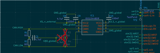
Customer is using the ISO1044 to a non-isolated application (GND1 and GND2 connected) but experienced hot issues during start up:

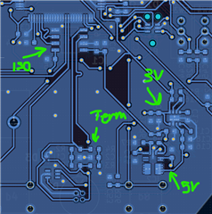
Have used this component in a lot of our products. And because of ease I have used it on boards that does not need the isolation. In one board i have a 5v buck converter that feeds a 3v buck converter and this supplies the card as well as both sides of the can isolator. Should this be an issue?

In this other case where is have the 5v and 3v. Is there any concern with powering them in this way? Because at start-up it gets really hot.

250kbit/s is the speed.
CAN classic mode

For your assistance.

Regards,
Archie A.

  • Hi Team,

    I asked scope measurements to supply pins but can't provide.

    They have a theory on what is happening. This system can be hot plugged and, in this case, the 5v starts before the 3v also rush current. Could this be the issue?

    They have a new design where the transceiver is disconnected from power until the mcu has started.

    73,
    Archie A.

  • Hello Archie, 

    Thank you for the explanation. I understand that you are not using the isolated functionality of the device. 

    The schematic looks good and functionally there shouldn't be an issue with the device. The problem is "the device gets hot at start-up", correct? 

    • Does this mean that the device cools down after the application has been running for a while? 
    • And please confirm that the device communicates as expected (and only the start-up heating is the concern)?

    The first thing I notice in the layout is the thin and long traces that connect to both the 5V and 3.3V rail. The below diagram shows the recommended PCB layout which uses a thicker trace width on VCCx and GND for better thermal performance. The ISO1044DEVM is an example of a layout with a larger ground connection. 

    Thinner traces will result in a higher resistance which may be the cause of heating during the hot swap event (due to the thin trace width and in-rush current). The customer should be able to test the effects of a thicker trace by soldering a thicker wire in parallel to the trace from VCCx to the decoupling capacitor on VCCx 

    Best,
    Andrew

  • Hi Andrew,

    Thank you for your guidance.

    Noted on this. Customers have a new design with thicker traces as well as a shutdown MOSFET that turns on the transceiver when the system has started.

    That should hopefully prevent any problems.

    Any further advise to share is highly appreciated.

    Regards,
    Archie A.

  • Archie,

    Thank you for the update. Let me know if the customer’s new design fixes the issues. I will close the post now.