This thread has been locked.

If you have a related question, please click the "Ask a related question" button in the top right corner. The newly created question will be automatically linked to this question.

SN6507-Q1: Maximum output capacitance

Part Number: SN6507-Q1
Other Parts Discussed in Thread: SN6505B-Q1, SN6507, DRV3901-Q1, , SN6505B, TPS25947, TPS25940-Q1

Tool/software:

Hello,

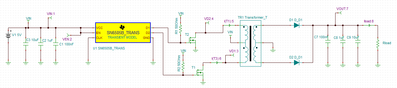
I am having 5V input and 15V output. My current consumption is greater than 2A so I am using external MOSFET comprimisng current limit.

I want to add bulk capacitance at the output say 1000uF for maintaing the power in case of loss of supply.

The datasheet recommends output capacitance Cout < (10*Css). Let's say my Css is 1.2uF (Tss=5ms) then maximum Cout would be maximum 12uF.

In this case soft start will work or do you recommend SN6505B-Q1 which has a fixed soft start that can solve the issue?

Thank you,

  • Hello Vishwas,

    Is this 2A mentioned is a continuous output requirement or peak current during load transient? If it is load transient, what is the time duration? 

    For SN6507 over current protection is disabled during soft-start. After soft-start finishes, the OCP is enabled. In case of an extreme over-load condition on the isolated output due to a short circuit, the device behaves as follows, 

    1.  In the event of a transient overload or short circuit, if the resulting voltage dip is lower than 2.5 V (typical) on the SS/ILIM pin, the device considers it as a “soft-short” condition. In soft-shorts, the converter goes into hiccup mode: on hitting the programmed OCP threshold, the driver will be shut-off for 100 ns (typical), and then retry driving. If the OCP trips again, the cycle continues. This retry keeps occurring for entire TON time of SW1 and SW2 until OCP does not trip or a "hard-short" is triggered. During the OCP retry events, both FETs are turned OFF, and the transient peak current may go higher than OCP limit.
    2. If the voltage dip is more than 2.5 V (typical), the devices considers it as a “hard-short” condition. The hard-short OCP threshold is fixed at 5 A (typical). If a hard-short condition lasts more than 200 μs, it indicates that the system is in a serious short-circuit fault condition, the device will fully discharge the soft-start cap and enters soft start once the short circuit is cleared. Note there is a 65 ns (typ.) response time to trigger hard-short OCP.

    Regards, S Mathew. 

  • Hello Mathew,

    Actually I am using DRV3901-Q1 at the output of push pull so 2A is for 0.5ms only.

    Thank you,

  • Hi Vishwas,

    SN6505 typical soft start time is 4.25ms and will be able to support required load transients. But if the output cap value is higher than specified the device will enter in OCP. For higher capacitor values it is better to have an additional slew rate control circuit.

    Regards, S Mathew

  • Hello Mathew,

    ok understood. Also, I need to design SN6507-Q1 with external mosfet right because during deployment it will take 2A for 0.5ms so the device will go to current limit.

    Thank you,

  • Hello Mathew,

    ok understood. Also, I need to design SN6507-Q1 with external mosfet right? because during deployment it will take 2A for 0.5ms so the device will go to current limit which needs to be avoided.

    If i want to design SN6507/ SN6505B with external MOSFET the gate of the MOSFET will be always ON and during the initial condition both MOSFET will be ON. 

    So, using this configuration the soft start will not work right?

    Also, what will happen to the system since both MOSFET are ON?

    Reference link: 12V Transformer driver for isolated gate drive power supply requirements - Isolation forum - Isolation - TI E2E support forums

    Thank you,

  • Hi Vishwas,

    Yes, your understanding is correct. In the above mentioned configuration both the MOSFET will be ON and the current may not control as required. The design required slew rate control and current control on the secondary side for proper functioning. Please check the possibility of using TPS25947 type device for adjustable slew rate and current.

    Regards, S Mathew. 

  • Hello Mathew,

    Ok, secondary side as recommended we can use TPS25947 for inrush current and peak current.

    But, during the initial condition when both the MOSFET are ON the primary side of transformer acts as short right? Then it would be problem for the transformer right.

    Thank you,

  • Hi Vishwas,

    In this configuration D1 & D2 are the switch nodes and T1, T2 gate will follow the same switching pattern. 

    Regards, S Mathew. 

  • Hello Mathew,

    Sorry, I didn't get you.

  • Hi Vishwas,

    After initial turn ON, the SN6507 switch nodes D1, D2 which connected to T1, T2 gate will follow the same push-pull switching pattern.

    Regards, S Mathew. 

  • Hello Mathew,

    I have one more query. Let’s say I have soft start time 5ms and 1mF capacitor.

    To charge to 14V it requires inrush current of 2.8V.

    It is mentioned in datasheet that during soft start overcurent protection will be disabled.

    So, is it fine right the device will handle this current without turning off internal mosfets.

    Or will the junction temperature rises and goes thermal shutdown. If yes, could you please share calculator what are the factors you considered.

    Thank you,

  • Hi Vishwas,

    The recommended max switch current is 0.5A. The small die of the SN6507 will heat up and may reach thermal limit and shutdown at 170°C if the device is switching too long beyond the specified condition.  

    Regards, S Mathew. 

  • Hello Mathew,

    Ok, understood.

    I can see TPS25947 is not AEC qualified. Any other alternate part?

    Thank you,

  • Hi Vishwas,

    Please check TPS25940-q1.

    Regards, S Mathew.