This thread has been locked.

If you have a related question, please click the "Ask a related question" button in the top right corner. The newly created question will be automatically linked to this question.

ISOUSB111:Regarding malfunctions of ISOUSB111

Part Number: ISOUSB111

Tool/software:

Hello.
When I changed ADuM3160 to ISOUSB111, it started working strangely.
Please tell me how to solve this problem.

UD+/UD- are connected to USB microB and DD+/DD- are connected to the MCU's USB D+/D-.
The USB microB is connected to the PC with a USB cable.
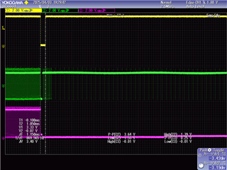
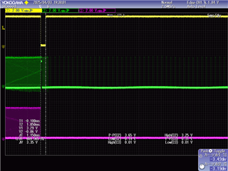
The PC sends a command, which causes the MCU to soft reset.
After the reset, the PC cannot see the MCU, and it does not move on to the next sequence.
Can ISOUSB111 be used with USB microB?

  • Hi Yusuke-san,

    Thank you for reaching out and sorry to hear about the issue.
    Can you please share the following to understand the issue better?

    1. Schematic
    2. Share waveform of UD± and DD± of ISOUSB111 when the issue occurs, possibly showing the data mismatch between the two
    3. Did you test multiple PCBs and does this happen with multiple PCBs?

    We don't expect ISOUSB111 to have any issues in working with USB Micro-B connector as the protocol remains the same and there is only a physical change in connector type.


    Regards,
    Koteshwar Rao

  • Hello, Rao-san
    Thank you for your reply.

    > 2.Share waveform of UD± and DD± of ISOUSB111 when the issue occurs, possibly showing the data mismatch between the two

    When the issue occurs, DD± cannot check the waveform (after MCU reset)

    > 3.Did you test multiple PCBs and does this happen with multiple PCBs?

    This occurs on multiple PCBs.
    Sometimes communication is successful, but this problem occurs about 30% of the time.

  • Sorry, I mistakenly marked this as resolved.
    Please let us continue our discussion.

  • Hi Yusuke-san,

    I understand you accidentally marked this as Resolved, we can continue the discussion.

    When the issue occurs, DD± cannot check the waveform (after MCU reset)

    Can you elaborate what do you mean by this?
    Did you mean to say that it would be difficult to capture the waveform when the issue occurs? Or there are no waveforms when issue happens?
    I am looking for waveform that shows UD± and DD± when the issue happens. i.e., a few 100s of µs before and 100s of µs after the issue.

    Please do share the schematic as well for review.
    In addition, it would also help to test the solution by inserting a USB hub between PC and ISOUSB111 and test, only for the debug purposes. Let me know if you will be able to do this test, thanks.


    Regards,
    Koteshwar Rao

  • Hello, Rao-san
    Thank you for your reply.
    I was able to capture the waveform when the problem occurred.

    Does this tell you anything?
    I'm currently checking with the company about the circuit.

    The configuration is as follows:
    PC (USB micro B) → ISOUSB111 (SSOP) → AT91SAM (USB Port)

    Yellow: Trigger (CPU RESET), Green: UD+, Purple: DD+

    Yellow: Trigger (CPU RESET), Green: UD+, Purple: DD+

    Yellow: Trigger (CPU RESET), Green: UD-, Purple: DD-

    Regards,
    Yusuke Oodaira

  • Hi Yusuke-san,

    Sorry, I couldn't make out anything from the waveform shared.
    May I know what is Trigger waveform? I would like to see UD± and DD± all in the same capture so that I can compare if the device is causing any data mismatch.

    I will also wait for the schematic for review, thanks.


    Regards,
    Koteshwar Rao

  • Hello, Rao-san
    Thank you for confirming.
    I am unable to obtain UD± and DD± waveforms simultaneously.
    I will give up using this device.
    Thank you for your assistance.
    Regards,
    Yusuke Oodaira