Other Parts Discussed in Thread: ADS131M04EVM, , ISOUSB211, USB2ANY, ADS131M04
Tool/software:
Hi,
Let me ask you a very basic question.
I would like to try to connect this EVM with ADS131M04EVM.
That is to say,
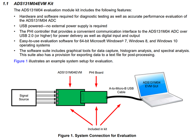
AMP(analog signal out) --- ADS131M04EVM --- ISOUSB211DPEVM --- PC
As I'm not familiar with ISOUSB211 and USB specificationss,
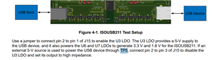
please let me know the jumper settings on the ISOUSB211DPEVM to connect with ADS131M04EVM.
And to connect ADS131M04EVM, should we prepare external power supply for ISOUSB211?
Thank you for your support.
Best Regards,
Takumi