This thread has been locked.

If you have a related question, please click the "Ask a related question" button in the top right corner. The newly created question will be automatically linked to this question.

ISO7741: Layout impedance control of isolator input and output

Part Number: ISO7741

Tool/software:

Hi Team,

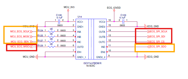
We're using the ISO7741FBDWR, ISO7742FDBQR and ISO7740FQDWRQ1 in our product.

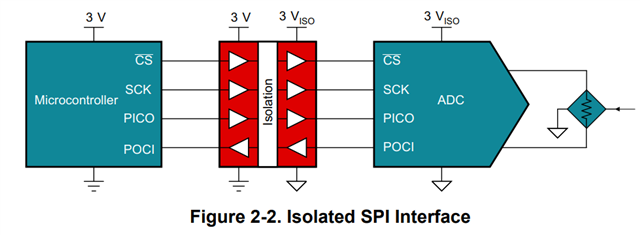
These isolators are being used for SPI communication and GPIO signals.

We have implemented the following routing strategy:

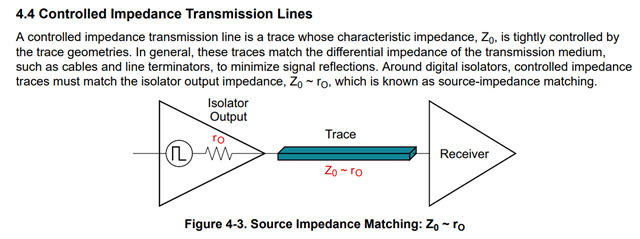
  • Maintaining 70-ohm impedance between the isolator outputs (OUTA, OUTB, OUTC, OUTD) and the receiver inputs.

  • Maintaining 50-ohm impedance between the isolator inputs (INA, INB, INC, IND) and the driver outputs.

We are referring to the guidelines provided in the following TI application note:

https://www.ti.com/lit/an/slla284g/slla284g.pdf?ts=1742279592311

Is this ok to route the signals like above? 

Kindly review and let us know if the above routing is appropriate or if any changes are recommended.

Thanks!

  • Hi Sneha,

    Thank you for reaching out. 

    The snippet from the App note, "Digital isolator Design Guide", refers to the trace impedance. The trace impedance would depends on how long the trace is and the geometry of the trace itself. Considering this I am confused on what exactly the request is since it mainly depends on your PCB layout and system related requirements for source impedance. Can you please provide some more information regarding background, schematic, and PCB layout?

    Regards,
    Aaditya V

  • Hi Aaditya,

    Thanks for the response.

    We have routed the signals as follows:

    • Input side of the isolators (yellow boxes): 50-ohm impedance using 6 mil trace width

    • Output side of the isolators (red boxes): 70-ohm impedance using 6 mil trace width

    Could you please confirm if this routing approach is acceptable?

    Is it necessary to maintain 70-ohm impedance on both input and output sides, or is it sufficient to maintain 70-ohm only on the output side, considering the isolators are driving longer traces on that end?

    Awaiting for your response!

    Thanks!

  • Hi Sneha,

    Is it necessary to maintain 70-ohm impedance on both input and output sides, or is it sufficient to maintain 70-ohm only on the output side, considering the isolators are driving longer traces on that end?

    Since you have higher trace lengths from what you have mentioned, maintaining the trace impedance for both input and output would be important. By matching the input and output impedance and the trace impedance, you can minimize the reflections and related issues. Please allow me to confirm with my team and get back to you regarding your questions.

    Regards,
    Aaditya V

  • Hi Aaditya,

    Thanks, Kindly confirm this ASAP.

  • Hi Sneha,

    Thank you for your patience. 

    If the trace length is short for either side, trace impedance and source impedance matching is not a big concern. If the trace is considerably longer, then it is better to match the impedance of the traces to the source of the signal being driven.

    Regards,
    Aaditya