This thread has been locked.

If you have a related question, please click the "Ask a related question" button in the top right corner. The newly created question will be automatically linked to this question.

SN6507-Q1: Dummy load requirement for wide range input

Part Number: SN6507-Q1
Other Parts Discussed in Thread: SN6507

Tool/software:

Hello,

I have input of 10V to 16V, typical 12V and max of 24V for few ms.

I am choosing turns ratio of 2.8 with duty cycle control to regulate around 16V.

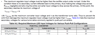
The datasheet recommends LDO or next circuit after push pull driver output to be 24*2.8 = 67.2V.

1. During what condition this voltage will appear?

2. I have my next circuits rated for 30V-40V only. Do I need to connect dummy resistor or zener to maintain regulated output of 16V always?

3. What is the minimum load requirement and recommendation to maintain regulated output? (I cannot choose next circuits rated for 100V)

Thank you,

  • Hi Vishwas,

    With duty cycle control feature the duty cycle will adjust with VIN, so that VOUT can be kept constant. The duty cycle control can compensate for input variation up to ±35%, where line regulation within ±5% can be achieved. To achieve this range, it is recommended that duty cycle at nominal VIN is centered at 25% (D = 0.25). The transformer turns ratio needs take this duty cycle into calculation to ensure the expected output voltage level at all VIN voltages (refer datasheet Section 9.2.2.5). To enable the duty cycle control feature, an inductor is required on the output side. The selection of the output inductor should make sure the inductor current will not go into discountinous conduction mode (DCM), meaning the inductor current ramp should not drop to zero at any time.

     The load does drop output voltage a little bit and when there is no load, the output is expected to be slightly higher like 10-20% than average load. SN6507 is an open-loop push-pull transformer driver where there is no feedback from secondary to primary, therefore, the device doesn't regulate the output and hence, no load regulation. If required a better regulation use a post-regulator like LDO.

    SN6507 EVM is designed with 10mA of dummy load. It is better to choose the resistor value proportionately to have 10mA dummy load current.

    Thanks.


  • Hello Mathew,

    I couldn't see any dummy resistor value in the schematic that is consuming 10mA. How you are telling it consumes 10mA?

    Thank you,

  • Hi Vishwas,

    Apologies for the error, the EVM is having 10K resistor. 

    Thanks. 

  • Hello Mathew,

    Ok, you are referring to R3 as 10k not 10mA. Which means if output is 15V then current would be around 1.5mA.

    Thank you