


Tool/software:
Dear Team,
Greetings!
We are planning to use the ISOM8610 solid-state relay (SSR) to isolate the microcontroller outputs from the high-voltage DC (HVDC) side in our custom motor control board. The target load is an inductive fan motor with a maximum current rating of 1A.
Since the ISOM8610 cannot handle 1A through its output pins (S1/S2), we are using it only to drive the gate of an external MOSFET. This MOSFET will provide the return path for the motor current.
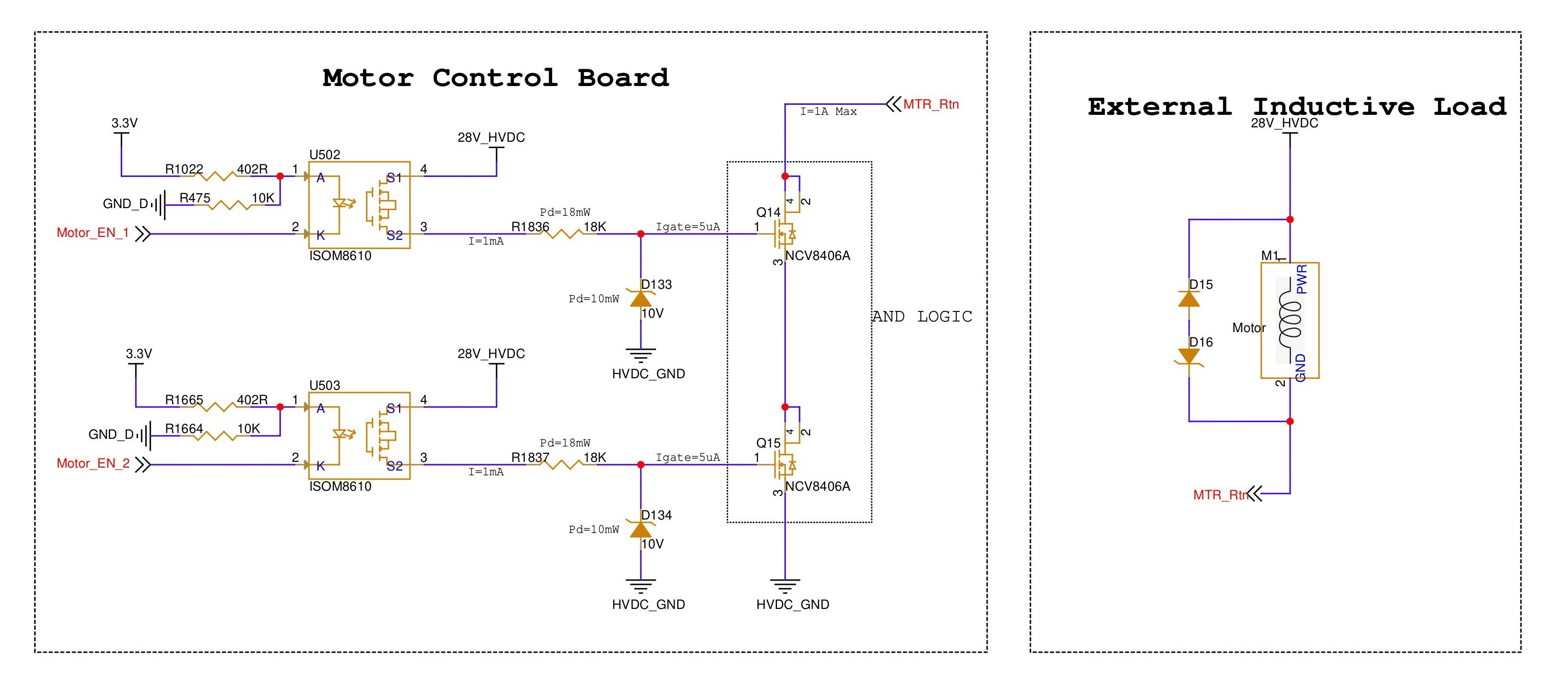
We are receiving two independent logic signals: Motor_EN_1 and Motor_EN_2. To ensure the motor turns on only when both enables are active, we have configured the external MOSFETs in a series (ANDed) configuration. The schematic snippet is attached for your reference.
One point of concern is that we have placed a resistor and Zener diode at the S2 pin of the SSR to clamp it to 10V, rather than grounding the source pin it directly. We would like to confirm:
-
Will this configuration provide sufficient VGS ( i,e is VGS > VGSTH) to turn on the internal MOSFET of the SSR?
-
Will the SSR operate correctly in this configuration?
Your feedback on whether this design approach is valid and safe for switching the inductive load is greatly appreciated.
Best regards,
Sameep Pai K S
