


Tool/software:
I hope this message finds you well.
We are currently considering the adoption of the ISO1228. In the circuit we plan to use, an input current of over 10mA is required.
However, according to the datasheet, the maximum input current for the ISO1228 is specified as 3.5mA. This presents a challenge in using the ISO1228 as intended.
To address this issue, we are contemplating the addition of a load resistor on the input side to divert the current accordingly.
Questions:
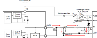
Is it acceptable to attach a load resistor to the ISO1228? The circuit in question is similar to the one depicted in "Digital Input Module, Digital Output Module, Figure 6."
If it is acceptable, can the VIH and VIL calculations be performed using the method described in the datasheet?
We would greatly appreciate your prompt response to these inquiries.
Best regards,
